1.3 Model Numbers
1-5
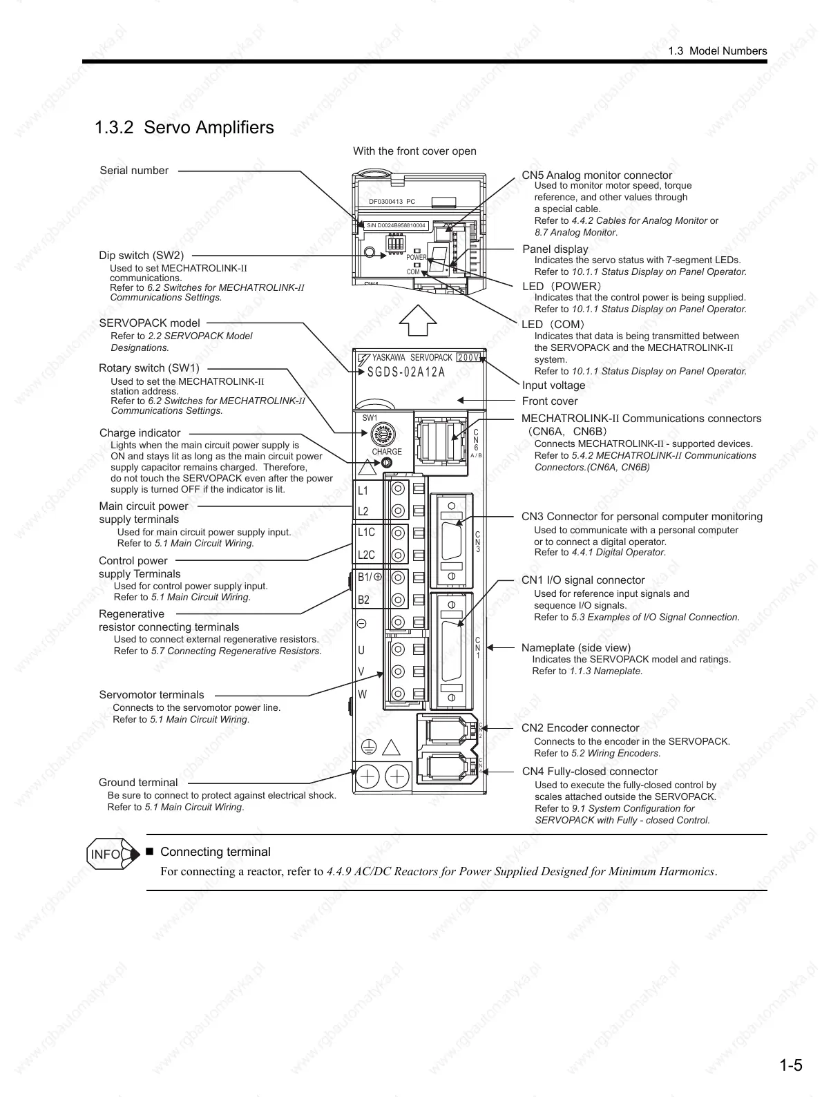
1.3.2 Servo Amplifiers
Connecting terminal
For connecting a reactor, refer to 4.4.9 AC/DC Reactors for Power Supplied Designed for Minimum Harmonics.
CN5 Analog monitor connector
Used to monitor motor speed, torque
reference, and other values through
a special cable.
Refer to 4.4.2 Cables for Analog Monitor or
8.7 Analog Monitor.
Indicates the servo status with 7-segment LEDs.
Refer to 10.1.1 Status Display on Panel Operator.
Indicates that the control power is being supplied.
Refer to 10.1.1 Status Display on Panel Operator.
Indicates that data is being transmitted between
the SERVOPACK and the MECHATROLINK-II
system.
Refer to 10.1.1 Status Display on Panel Operator.
Connects MECHATROLINK-II - supported devices.
Refer to 5.4.2 MECHATROLINK-II Communications
Connectors.(CN6A, CN6B)
Refer to 4.4.1 Digital Operator.
Refer to 2.2 SERVOPACK Model
Designations.
Used to set MECHATROLINK-II
communications.
Refer to 6.2 Switches for MECHATROLINK-II
Communications Settings.
Used to set the MECHATROLINK-II
station address.
Refer to 6.2 Switches for MECHATROLINK-II
Communications Settings.
Refer to 5.1 Main Circuit Wiring.
Used to connect external regenerative resistors.
Refer to 5.7 Connecting Regenerative Resistors.
Used for control power supply input.
Refer to 5.1 Main Circuit Wiring.
With the front cover open
Serial number
Charge indicator
Lights when the main circuit power supply is
ON and stays lit as long as the main circuit power
supply capacitor remains charged. Therefore,
do not touch the SERVOPACK even after the power
supply is turned OFF if the indicator is lit.
CN3 Connector for personal computer monitoring
Used to communicate with a personal computer
or to connect a digital operator.
CN1 I/O signal connector
Used for reference input signals and
sequence I/O signals.
Refer to 5.3 Examples of I/O Signal Connection.
CN2 Encoder connector
Connects to the encoder in the SERVOPACK.
Refer to 5.2 Wiring Encoders.
Ground terminal
Be sure to connect to protect against electrical shock.
Main circuit power
supply terminals
Used for main circuit power supply input.
Refer to 5.1 Main Circuit Wiring.
Control power
supply Terminals
Servomotor terminals
Connects to the servomotor power line.
Refer to 5.1 Main Circuit Wiring.
Nameplate (side view)
Indicates the SERVOPACK model and ratings.
Refer to 1.1.3 Nameplate.
SERVOPACK model
Front cover
Regenerative
resistor connecting terminals
Input voltage
CN4 Fully-closed connector
Used to execute the fully-closed control by
scales attached outside the SERVOPACK.
Refer to 9.1 System Configuration for
SERVOPACK with Fully - closed Control.
YASKAWA SERVOPACK
200V
SGDS-02A12A
SW1
CHARGE
L1
L2
L1C
L2C
B1/
B2
U
V
W
C
N
6
C
N
3
C
N
1
C
N
2
C
N
4
A / B
DF0300413 PC
ON
1
POWER
COM
S/N D0024B958810004
LED POWER
Panel display
LED COM
Dip switch (SW2)
MECHATROLINK-II Communications connectors
CN6A CN6B
Rotary switch (SW1)
INFO
 Loading...

