4.4 Peripheral Devices
4-9
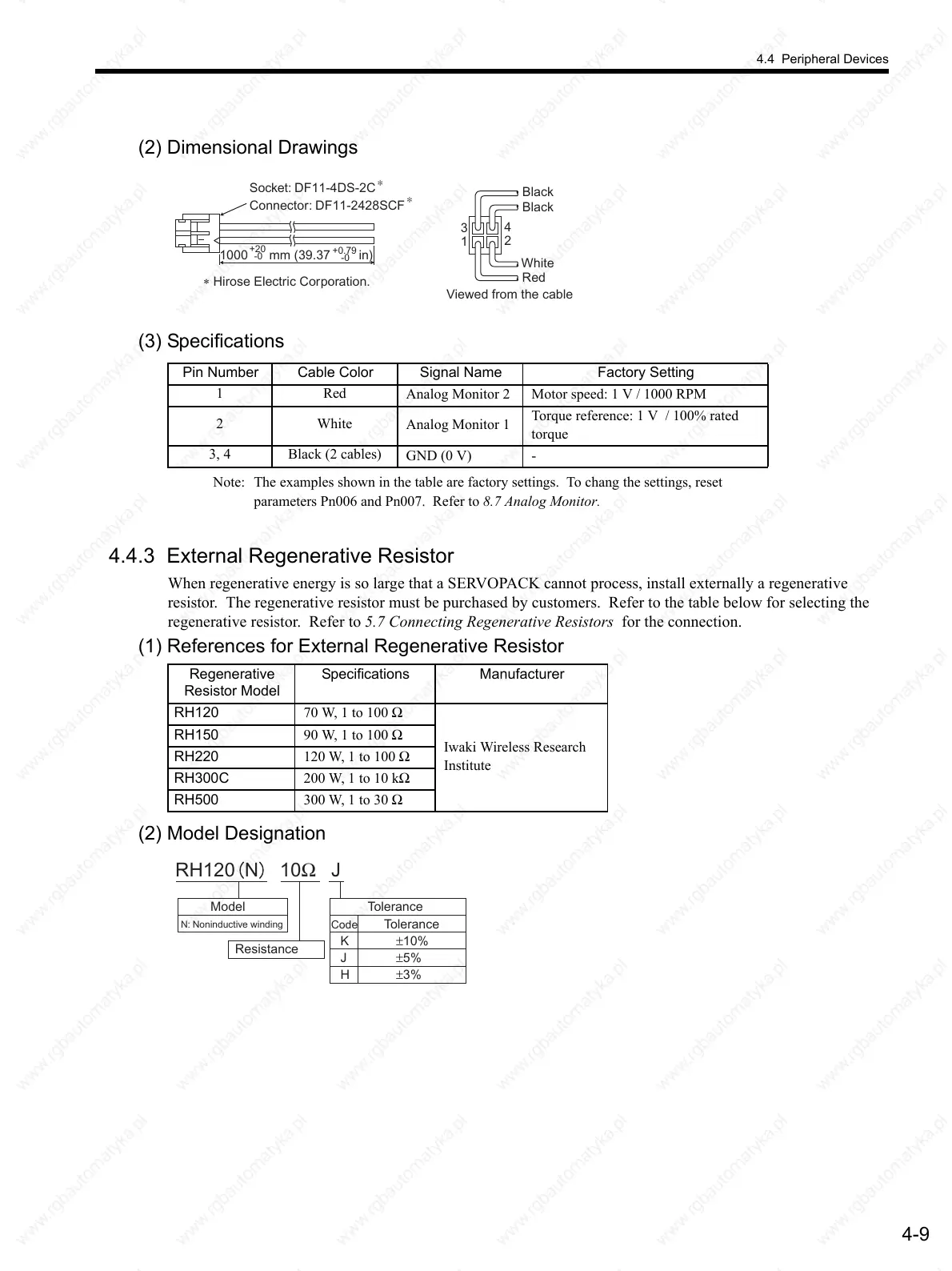
(2) Dimensional Drawings
(3) Specifications
Note: The examples shown in the table are factory settings. To chang the settings, reset
parameters Pn006 and Pn007. Refer to 8.7 Analog Monitor.
4.4.3 External Regenerative Resistor
When regenerative energy is so large that a SERVOPACK cannot process, install externally a regenerative
resistor. The regenerative resistor must be purchased by customers. Refer to the table below for selecting the
regenerative resistor. Refer to 5.7 Connecting Regenerative Resistors for the connection.
(1) References for External Regenerative Resistor
(2) Model Designation
Socket: DF11-4DS-2C
Connector: DF11-2428SCF
1000 mm (39.37 in)
-0
+20
-0
+0.79
∗
∗
∗ Hirose Electric Corporation.
3
4
1
2
White
Red
Black
Black
Viewed from the cable
Pin Number Cable Color Signal Name Factory Setting
1Red
Analog Monitor 2 Motor speed: 1 V / 1000 RPM
2White
Analog Monitor 1
Torque reference: 1 V / 100% rated
torque
3, 4 Black (2 cables)
GND (0 V) -
Regenerative
Resistor Model
Specifications Manufacturer
RH120 70 W, 1 to 100 Ω
Iwaki Wireless Research
Institute
RH150 90 W, 1 to 100 Ω
RH220 120 W, 1 to 100 Ω
RH300C 200 W, 1 to 10 kΩ
RH500 300 W, 1 to 30 Ω
RH120 N 10Ω J
Model
N: Noninductive winding
Tolerance
Resistance
Code
K
J
H
±10%
±5%
±3%
Tolerance
 Loading...

