8 Adjustments
8-50
8.7 Analog Monitor
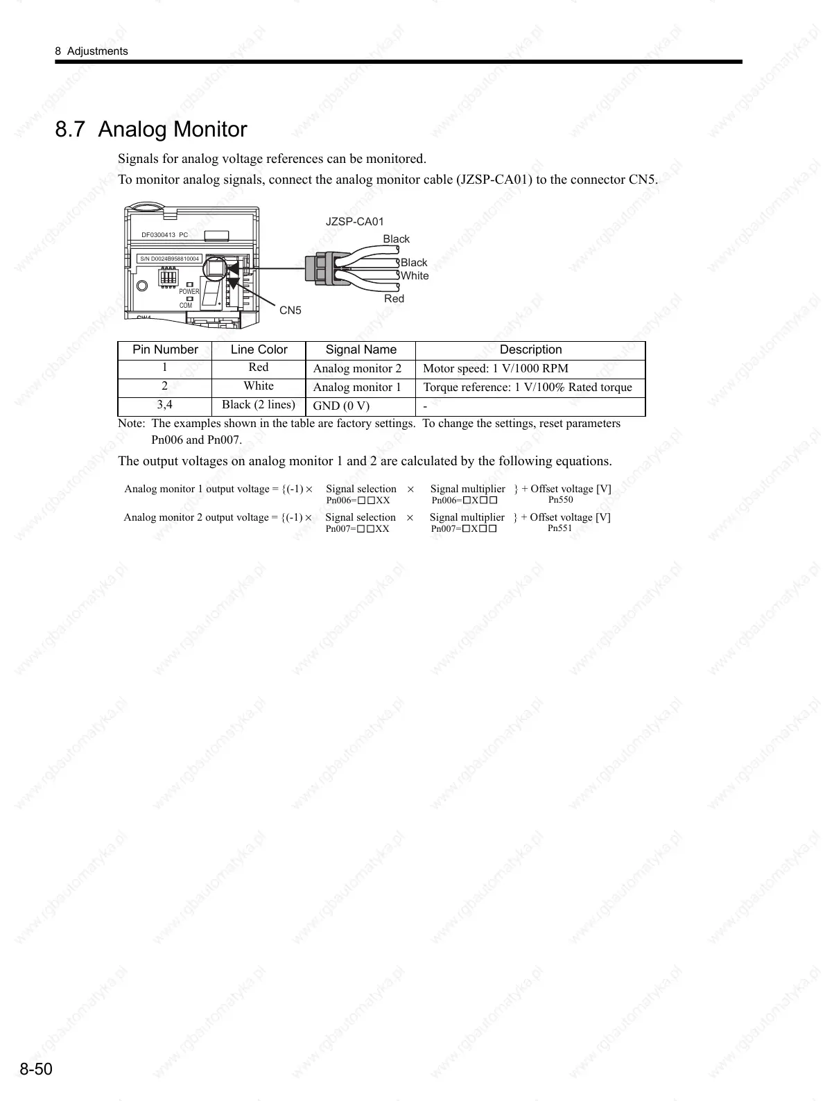
Signals for analog voltage references can be monitored.
To monitor analog signals, connect the analog monitor cable (JZSP-CA01) to the connector CN5.
Note: The examples shown in the table are factory settings. To change the settings, reset parameters
Pn006 and Pn007.
The output voltages on analog monitor 1 and 2 are calculated by the following equations.
Pin Number Line Color Signal Name Description
1Red
Analog monitor 2 Motor speed: 1 V/1000 RPM
2White
Analog monitor 1 Torque reference: 1 V/100% Rated torque
3,4 Black (2 lines)
GND (0 V) -
JZSP-CA01
Black
CN5
Black
Red
White
DF0300413 PC
ON
1
POWER
COM
S/N D0024B958810004
Analog monitor 1 output voltage = {(-1) × Signal selection × Signal multiplier } + Offset voltage [V]
Pn006= XX
Pn006=
X
Pn550
Analog monitor 2 output voltage = {(-1) × Signal selection × Signal multiplier } + Offset voltage [V]
Pn007= XX
Pn007=
X
Pn551
 Loading...

