3 SERVOPACK Specifications and Dimensional Drawings
3-2
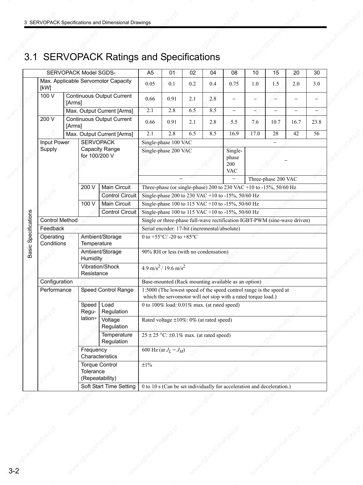
3.1 SERVOPACK Ratings and Specifications
SERVOPACK Model SGDS- A5 01 02 04 08 10 15 20 30
Basic Specifications
Max. Applicable Servomotor Capacity
[kW]
0.05 0.1 0.2 0.4 0.75 1.0 1.5 2.0 3.0
100 V Continuous Output Current
[Arms]
0.66 0.91 2.1 2.8 −−−−−
Max. Output Current [Arms]
2.1 2.8 6.5 8.5 − −−−−
200 V Continuous Output Current
[Arms]
0.66 0.91 2.1 2.8 5.5 7.6 10.7 16.7 23.8
Max. Output Current [Arms]
2.1 2.8 6.5 8.5 16.9 17.0 28 42 56
Input Power
Supply
SERVOPACK
Capacity Range
for 100/200 V
Single-phase 100 VAC
−
Single-phase 200 VAC Single-
phase
200
VA C
−
−−
Three-phase 200 VAC
200 V Main Circuit Three-phase (or single-phase) 200 to 230 VAC +10 to -15%, 50/60 Hz
Control Circuit Single-phase 200 to 230 VAC +10 to -15%, 50/60 Hz
100 V Main Circuit Single-phase 100 to 115 VAC +10 to -15%, 50/60 Hz
Control Circuit Single-phase 100 to 115 VAC +10 to -15%, 50/60 Hz
Control Method Single or three-phase full-wave rectification IGBT-PWM (sine-wave driven)
Feedback Serial encoder: 17-bit (incremental/absolute)
Operating
Conditions
Ambient/Storage
Temperature
0 to +55°C/ -20 to +85°C
Ambient/Storage
Humidity
90% RH or less (with no condensation)
Vibration/Shock
Resistance
4.9 m/s
2
/ 19.6 m/s
2
Configuration Base-mounted (Rack mounting available as an option)
Performance Speed Control Range 1:5000 (The lowest speed of the speed control range is the speed at
which the servomotor will not stop with a rated torque load.)
Speed
Regu-
lation∗
Load
Regulation
0 to 100% load: 0.01% max. (at rated speed)
Voltage
Regulation
Rated voltage ±10%: 0% (at rated speed)
Temperature
Regulation
25 ± 25
°C: ±0.1% max. (at rated speed)
Frequency
Characteristics
600 Hz (at J
L
= J
M
)
Torque Control
Tolerance
(Repeatability)
±1%
Soft Start Time Setting 0 to 10 s (Can be set individually for acceleration and deceleration.)
 Loading...

