7.5 Setting Up the SERVOPACK
7-27
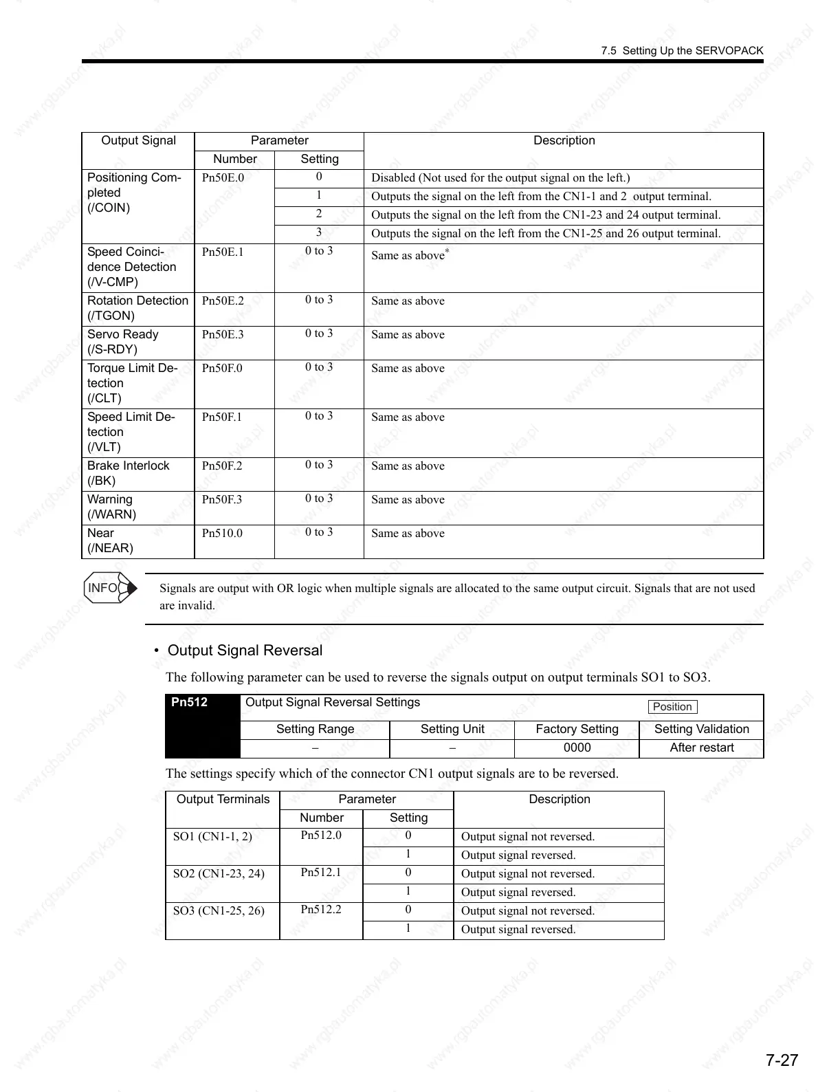
Signals are output with OR logic when multiple signals are allocated to the same output circuit. Signals that are not used
are invalid.
• Output Signal Reversal
The following parameter can be used to reverse the signals output on output terminals SO1 to SO3.
The settings specify which of the connector CN1 output signals are to be reversed.
Output Signal Parameter Description
Number Setting
Positioning Com-
pleted
(/COIN)
Pn50E.0
0
Disabled (Not used for the output signal on the left.)
1
Outputs the signal on the left from the CN1-1 and 2 output terminal.
2
Outputs the signal on the left from the CN1-23 and 24 output terminal.
3
Outputs the signal on the left from the CN1-25 and 26 output terminal.
Speed Coinci-
dence Detection
(/V-CMP)
Pn50E.1
0 to 3
Same as above
∗
Rotation Detection
(/TGON)
Pn50E.2
0 to 3
Same as above
Servo Ready
(/S-RDY)
Pn50E.3
0 to 3
Same as above
Torque Limit De-
tection
(/CLT)
Pn50F.0
0 to 3
Same as above
Speed Limit De-
tection
(/VLT)
Pn50F.1
0 to 3
Same as above
Brake Interlock
(/BK)
Pn50F.2
0 to 3
Same as above
Warning
(/WARN)
Pn50F.3
0 to 3
Same as above
Near
(/NEAR)
Pn510.0
0 to 3
Same as above
INFO
Pn512 Output Signal Reversal Settings
Setting Range Setting Unit Factory Setting Setting Validation
−−0000 After restart
Output Terminals Parameter Description
Number Setting
SO1 (CN1-1, 2)
Pn512.0 0
Output signal not reversed.
1
Output signal reversed.
SO2 (CN1-23, 24)
Pn512.1 0
Output signal not reversed.
1
Output signal reversed.
SO3 (CN1-25, 26)
Pn512.2 0
Output signal not reversed.
1
Output signal reversed.
Position
 Loading...

