11.2 List of Parameters
11-35
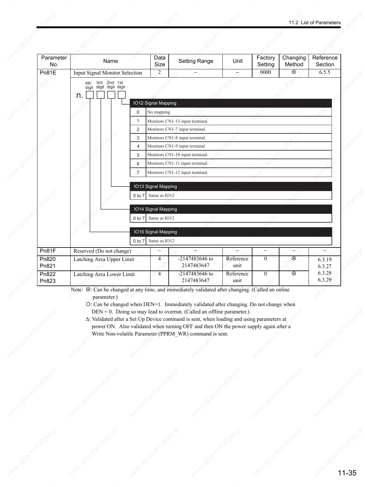
Pn81E Input Signal Monitor Selection
2 −−0000
6.5.5
Pn81F Reserved (Do not change)
−− −−−−
Pn820
Pn821
Latching Area Upper Limit
4 -2147483646 to
2147483647
Reference
unit
0
6.3.19
6.3.27
6.3.28
6.3.29
Pn822
Pn823
Latching Area Lower Limit
4 -2147483646 to
2147483647
Reference
unit
0
Note: : Can be changed at any time, and immediately validated after changing. (Called an online
parameter.)
: Can be changed when DEN=1. Immediately validated after changing. Do not change when
DEN = 0. Doing so may lead to overrun. (Called an offline parameter.)
∆: Validated after a Set Up Device command is sent, when loading and using parameters at
power ON. Also validated when turning OFF and then ON the power supply again after a
Write Non-volatile Parameter (PPRM_WR) command is sent.
Parameter
No.
Name
Data
Size
Setting Range Unit
Factory
Setting
Changing
Method
Reference
Section
0
1
2
3
No mapping
Monitors CN1-13 input terminal.
Monitors CN1-7 input terminal.
Monitors CN1-8 input terminal.
Monitors CN1-9 input terminal.
Monitors CN1-10 input terminal.
Monitors CN1-11 input terminal.
IO12 Signal Mapping
n.
4
5
6
7
Monitors CN1-12 input terminal.
Same as IO12
0 to 7
IO13 Signal Mapping
Same as IO12
0 to 7
IO14 Signal Mapping
Same as IO12
0 to 7
IO15 Signal Mapping
4th
digit
3rd
digit
2nd
digit
1st
digit
 Loading...

