User Parameter Tables
4-53
4
U1-34
OPE fault
parameter
Shows the first parameter
number when an OPE fault is
detected.
(Cannot be output.) - A A A 61H
OPE
Detected
U1-35
Zero sevo
movement
pulses
Shows the number of PG
pulses of the movement range
when zero servo was acti-
vated. The shown value is the
actual pulse numer times 4.
(Cannot be output.) - No No A 62H
Zero Servo
Pulse
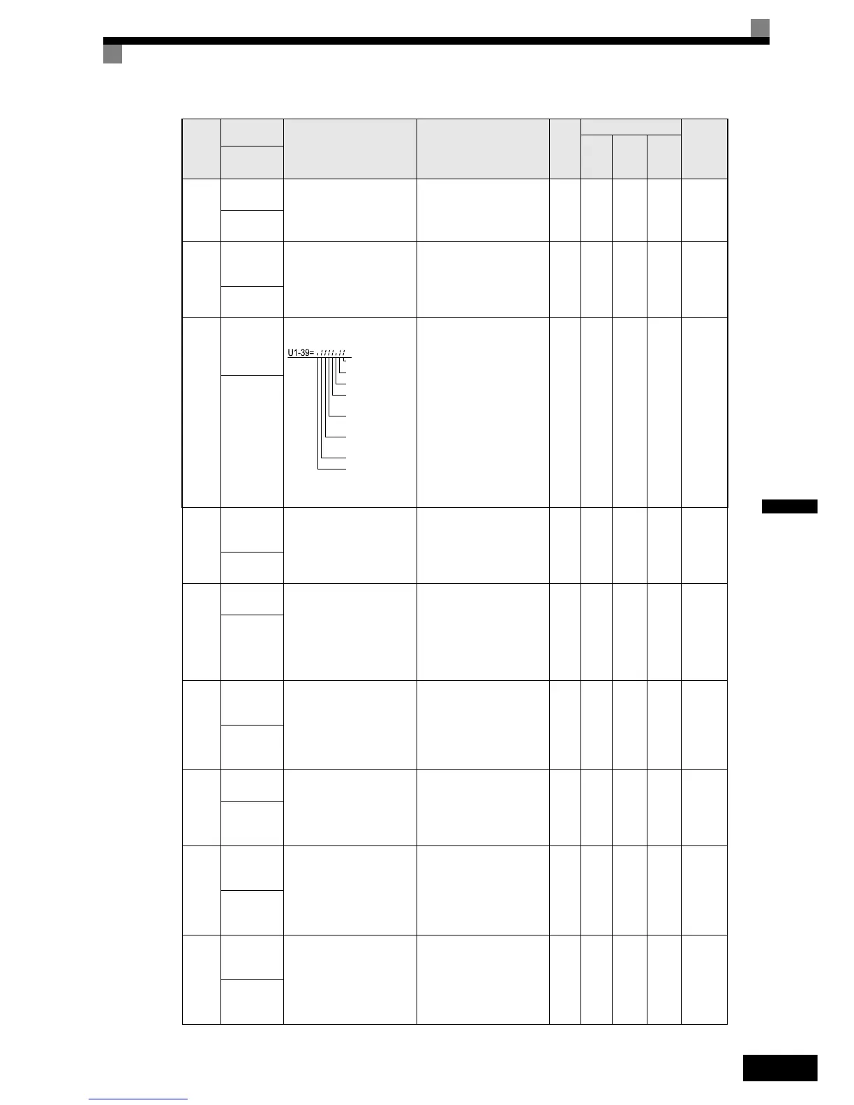
U1-39
MEMOBUS
communica-
tions error
code
Shows MEMOBUS errors.
(Cannot be output.) - A A A 66H
Transmit Err
U1-40
Cooling fan
operating
time
Monitors the total operating
time of the cooling fan. The
time can be set in
02-10.
(Cannot be output.)
1
hr
A A A 67H
FAN Elapsed
Time
U1-44
ASR output
without filter Monitors the output from the
speed control loop (i.e., the
primary filter input value).
100% is displayed for rated
secondary current of the
motor.
10 V: Rated secondary current
of motor
(-10 V to 10 V)
0.01
%
No No A 6BH
ASR Output
w Fil
U1-45
Feed for-
ward control
output
Monitors the output from feed
forward control. 100% is dis-
played for rated secondary
current of the motor.
10 V: Rated secondary current
of motor
(-10 V to 10 V)
0.01
%
No No A 6CH
FF Cout Out-
put
U1-50
Slip compen-
sation value
Monitors the slip compensa-
tion value.100% is displayed
for rated slip
10 V: Rated slip of motor
( -10 V to 10 V)
0.01
%
A A A 71H
Slip comp
value
U1-51
Max Current
during accel-
eration
Monitors the maximum curr-
net during acceleration.
10 V: Rated current of motor
(0 V to 10 V)
0.1 A A A A 72H
Max Amp
at accel
U1-52
Max Current
during decel-
eration
Monitors the maximum curr-
net during deceleration.
10 V: Rated current of motor
(0 V to 10 V)
0.1 A A A A 73H
Max Amp
at decel
Param-
eter
Number
Name
Description
Output Signal Level
During Multi-Function
Analog Output
Min.
Unit
Control Methods MEMO-
BUS
Regis-
ter
V/f
Open
Loop
Vector
Closed
Loop
Vector
Display
1: CRC error
1: Data length error
Not used
1: Parity error
1: Overrun error
1: Framing error
1: Timeout
http://nicontrols.com

 Loading...


