Control Sequence
5-15
5
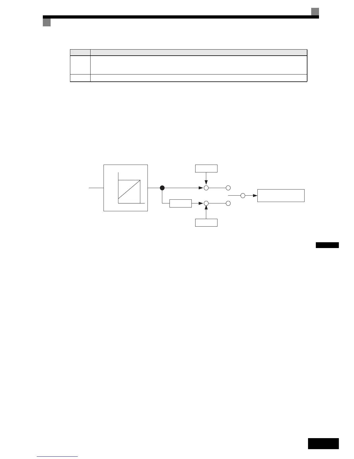
Torque compensation at start
If a load measuring device is installed in the elevator, in Closed Loop Vector mode an analog input can be used
to give a torque compensation value to the inverter.
The adjusted torque compensation value is latched when the direction command is given. At start it is
increased from zero to the latched value using the torque increase time set in parameter S1-22. The torque
compensation value is kept during the whole ride and is cleared when the direction command is removed.
The torque compensation function can be adjusted using the parameters shown in the block diagram below.
Adjust the parameter so that the torque compensation value is zero when the elevator is balanced.
t8-t9
The inverter continues zero speed operation until the time S1-05 – S1-07 time be passed.
Remove the direction signal .
The inverter shuts down the output voltage and the hardware base block signal must be set.
t9-t10 After the “Output contactor open delay time” (S1-19), the inverter releases the output contactor control signal.
Timing Description
H3-16
H3-17
0 10v
terminal A1
H3-15=1
torque
compensation
S1-25
S1-23
S1-24
++
+
+
UP
direction
DOWN
direction
Torque compensation
%
Torque compensation
bias during raising
Torque compensation bias
during lowering
Torque compensation gain
during lowering
http://nicontrols.com

 Loading...


