5-14
Brake Sequence with torque compensation at start
This sequence works in Closed Loop Vector control only. To use the brake sequence with torque compensation
at start,
• the A1 function must be selected for “Torque compensation” (H3-15=1) or
• one of the input channels Ch2 or Ch3 of the optional analog input card AI-14B must be set to “Torque
Compensation” (H3-05,H3-09=14).
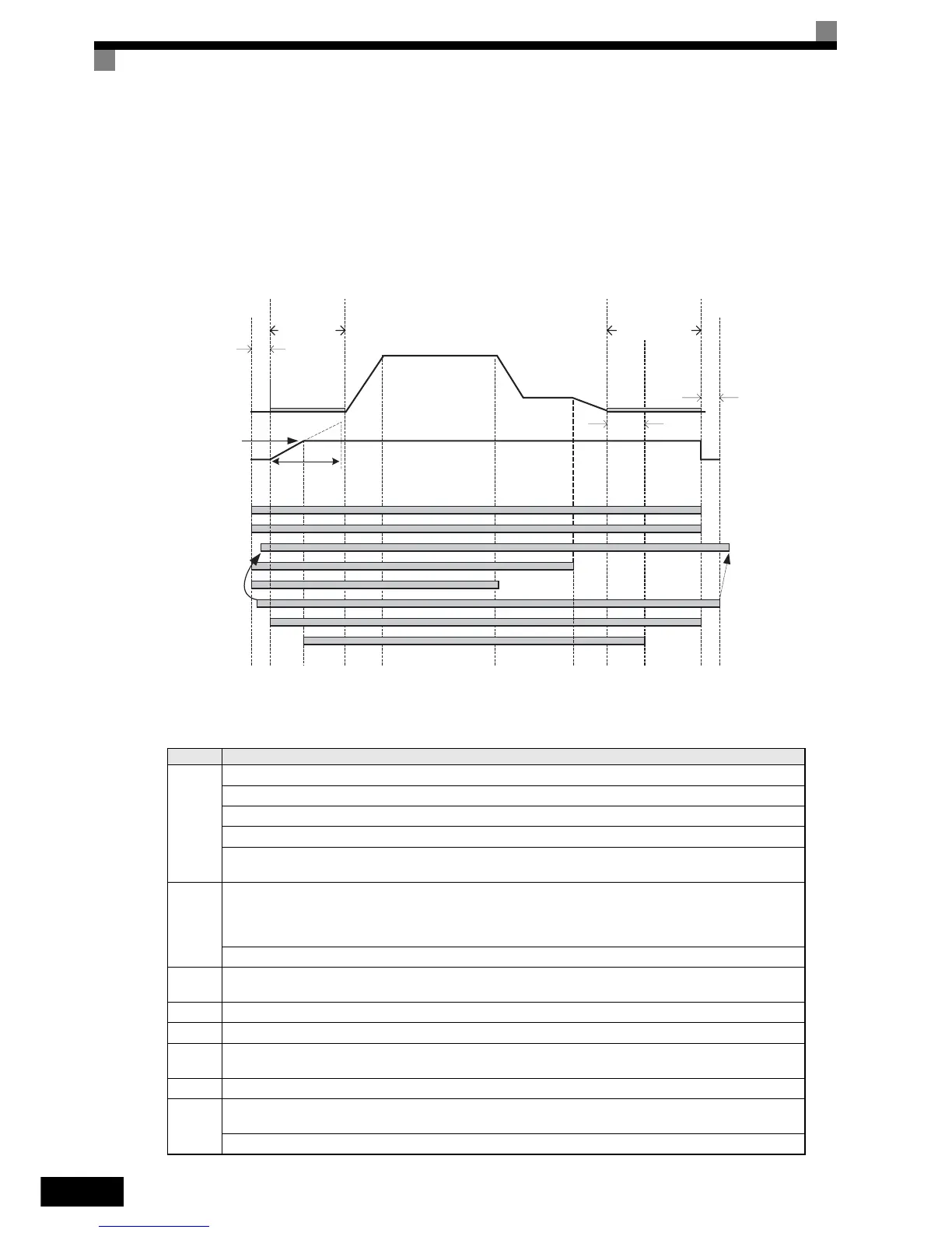
The figure below shows the timing chart for this breake sequence.
Fig 5.4 Timing chart of Brake sequence with torque compensation at start
The timing chart above is divided in time zones. The following table explains the sequence in each time zone
Timing Description
t0-t1
The inverter gets the direction signal (Forward/Reverse)
The inverter gets the hardware base block signal disable signal (Not BB condition).
The inverter receives the speed reference signal.
The inverter sets the contactor closed signal .
The inverter waits for the contactor confirmation signal. If no digital input is set for “ Contactor conformation
signal”, the sequence is proceeded after exceeding the operation start delay time (S1-16).
t1-t2
The Inverter will activate the output.
The zero speed operation is started.
The analog torque compensation value is latched and start producing the torque compensation value from Zero based on
the S1-22 (“Starting torque compensation increase time”.
After reaching torque comp level at start, the inverter sets the brake open and holds the torque compensation value until stop.
t2-t3
After passing zero speed operation time set in S1-04 , the inverter starts accelerating.
The Dwell at start function can be activated.
t3-t4 The inverter starts to accelerate.
t4-t5 The inverter speed reaches the selected speed.
t5-t6
When the leveling speed is selected, the inverter starts to decelerate .
The inverter keeps operating at the leveling speed.
t6-t7 Select 0 speed, the inverter ramps to stop.
t7-t8
The inverter reaches the zero speed.
The inverter keeps zero speed control.
After passing “Brake Close Delay Time(S1-07)” , the inverter sets the brake close.
Up/Donw D/I
Leveling speed selection D/I
Selected speed (D/I)
speed
Zero Speed
Control
S1-04
Zero Speed
Control
S1-05
Contactor Control D/O
Internal Run
Brake Control (D/O)
RUN Delay (200ms)
Brake Close
delay time
100ms
Contactor confirmation D/I
Inverter Hardware BB (D/I)
stop
t0 t1 t2 t3 t4 t5 t6 t7 t8 t9 t10
torque comp
level at start
Clear the
torque comp
Torque comp
increase time
S1-22
300%torque
S1-16
S1-07
S1-19
vn
vl
Contactor
open delay
http://nicontrols.com