Control Sequence
5-13
5
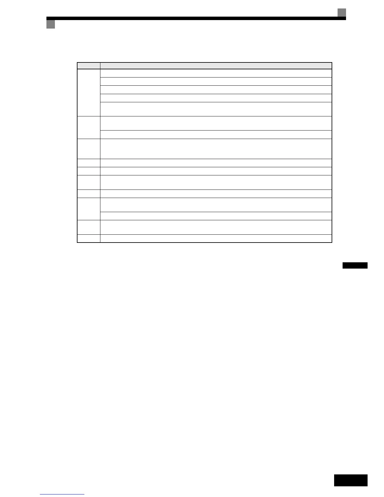
The timing chart above is divided in time zones. The following table explains the sequence in each time zone.
Timing Description
t0-t1
The inverter gets the direction signal (Forward/Reverse)
The inverter gets the hardware base block disable signal (Not BB condition).
The inverter receives the speed reference signal.
The inverter sets the contactor closed signal .
The inverter waits for the contactor confirmation signal. If no digital input is set for “ Contactor conformation
signal”, the sequence is proceeded after exceeding the operation start delay time (S1-16).
t1-t2
Inverter will activate the output after passing the “RUN Delay Time” (S1-16).
DC Injection/zero servo or zero speed operation is started.
After passing the “Brake Open delay time” (S1-06), the inverter starts opening the brake.
t2-t3
The inverter keeps DC injection/zero servo until
* the time S1-04 – S1-06 has exceeded if S1-06 < S1-04
* the time S1-06 has exceeded if S1-06 > S1-04 (try avoid this setting since the inverter could run against the brake)
t3-t4 The inverter starts to accelerate.
t4-t5 The inverter speed reaches the selected speed.
t5-t6
The speed is selection is changed to the leveling speed , the inverter starts to decelerate.
After reaching the leveling speed the inverter keeps operating at this speed.
t6-t7 The leveling signal is removed, the inverter ramps to stop.
t7-t8
The inverter reaches the zero speed.
The inverter starts DC injection/zero servo for the time set in S1-05.
After passing “Brake Close Delay Time” (S1-07) , the inverter activates the brake close command.
t8-t9
The inverter continues DC Injection/zero speed until S1-05 – S1-07 has time passed. Remove the direction signal .
The inverter shuts down the output voltage and the hardware base block signal must be set.
t9-t10 After the “Output contactor open delay time“ (S1-19) has passed, the inverter releases the output contactor control signal.
http://nicontrols.com