Digital Operator/Monitor Functions
5-59
5
Comparing Inverter Parameters and Digital Operator/Monitor Parameter Set Values
(VERIFY)
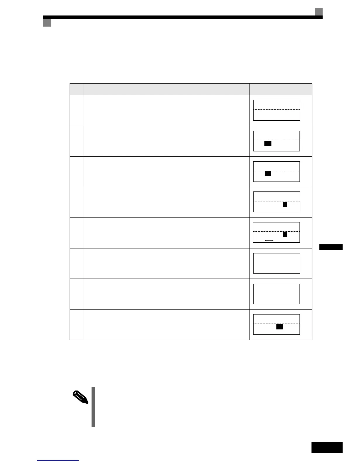
To compare Inverter parameters and Digital Operator/Monitor parameter set values, use the following method.
If an error is displayed, press any key to cancel the error display and return to the o3-01 display. Refer to
page 6-16, Digital Operator/Monitor Copy Function Faults for corrective actions.
Application Precautions
Table 5.3 VERIFY Function Procedure
Step
No.
Explanation
Digital Operator/Monitor Dis-
play
1 Press the MENU Key. and select advanced programming mode.
2 Press the DATA/ENTER Key.
3
Press the the Increment and Decrement Key unti the parameter o3-01 is displayed (Copy
Function Selection).
4 Press the DATA/ENTER Key and select the function setting display.
5 Change the set value to 3 using the Increment Key.
6 Set the changed data using the DATA/ENTER Key. The VERIFY function will start.
7 If the VERIFY function ends normally, “End” is displayed on the Digital Operator/Monitor.
8 The display returns to o3-01 when a key is pressed.
When using the copy function, check that the following settings are the same between the Inverter data and the Digital
• Operator/Monitor data.
• Inverter product and type
• Software number
• Inverter capacity and voltage class
• Control method
** Main Menu **
-ADV-
Programming
Initialization
-ADV-
A1 - 00 = 1
Select Language
COPY Function
-ADV-
o3
- 01=0
Copy Funtion Sel
Copy Function Sel
-ADV-
o3-01= 0
COPY SELECT
*0*
Copy Funtion Sel
-ADV-
o3-01= 3
*0*
OP INV VERIFY
VERIFY
-ADV-
DATA VERIFYING
VERIFY
-ADV-
VERIFY COMPLETE
Copy Function Sel
-ADV-
o3
-
01 = 0
COPY SELECT
*0*
INFO
http://nicontrols.com
 Loading...


