IM 04L20A01-01E
1-4
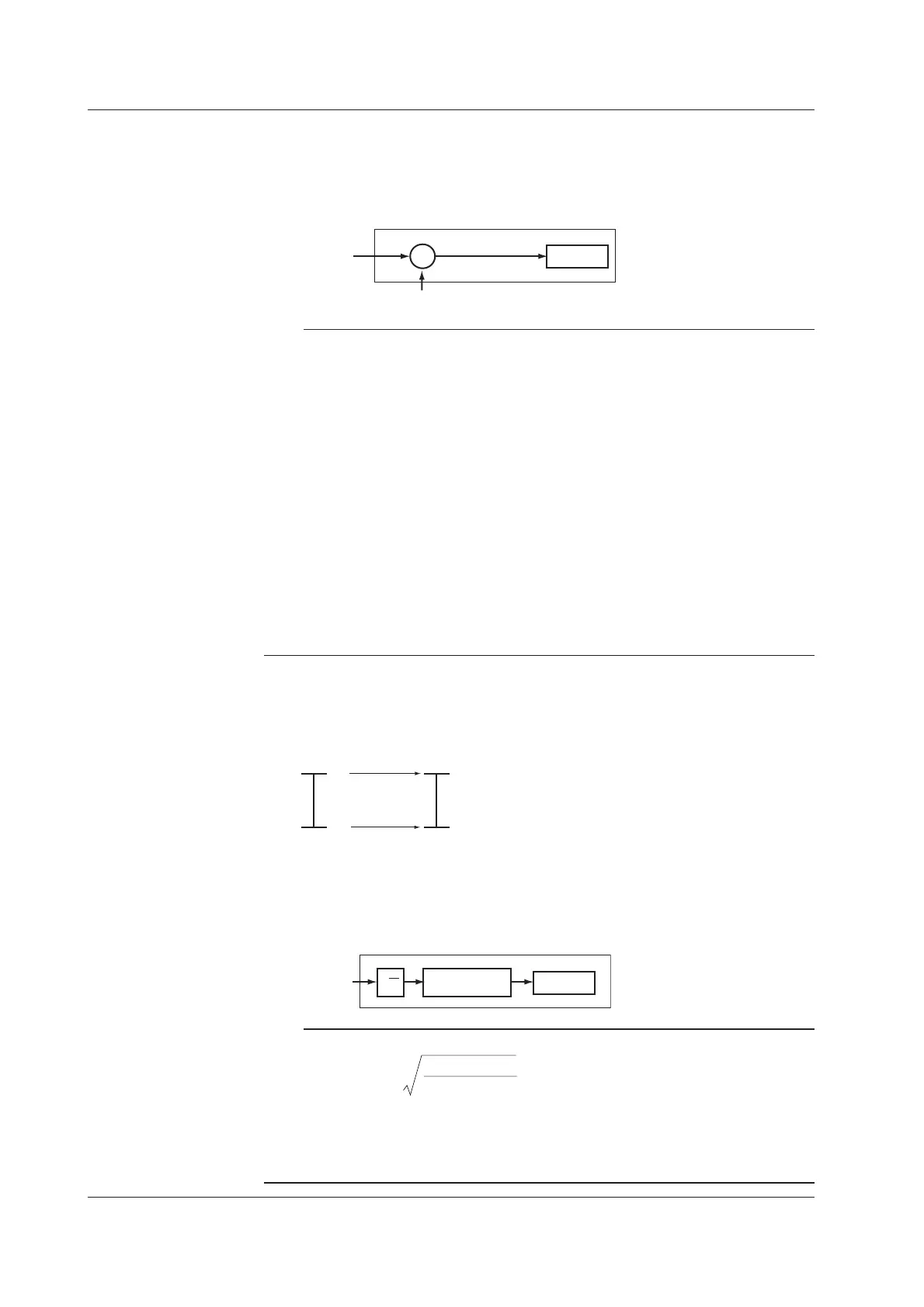
Difference Computation
The value obtained by subtracting the measured value of another channel (this
channel is called a “reference channel”) from the input value becomes a measured
value of the channel.
Input value
Measured value of the reference channel
Difference computation
Measured
value
−
+
Note
Even if the input type or the measurement range of the difference computation channel and
the reference channel is not the same, the difference computation is performed according to
the following rules.
• When the decimal position between the reference channel and the difference computation
channel is different, the measured value of the reference channel is adjusted to the
decimal position of the measured value of the difference computation channel to make the
computation.
Example: When the measured value of the difference computation channel is 10.00 and
the measured value of the reference channel is 100.0, the computation result becomes
10.00 – 100.0 = –90.00.
• When the units for the reference channel and the difference computation channel are
different, the measured value is not adjusted.
Example: When the measured value of the difference computation channel is 10.00 V and
the measured value of the reference channel is 5.00 mV, the computation result becomes
10.00 V – 5.00 mV = 5.00 V.
• When the reference channel is set to [Scale] or [Sqrt], the computation uses the scaled
values.
Scaling
The input value is converted to a value in the appropriate unit and the converted value
becomes a measured value of the channel.
1 V −100.0 °C
5 V 300.0 °C
Measured valueInput value
Square Root
When the input type is set to “DC voltage,” the square root of the input value is
computed. The computed result is scaled to a value in the appropriate unit and the
scaled value becomes a measured value of the channel.
Input value
Measured
value
√
Scaling
Square root computation
Note
• The FX100 uses the following square-root computation:
V – V
V – V
+ F
x
max min
max
F = (F – F )
x min min
min
• Vmin: Lower limit of span • Fmin: Lower limit of scale • Vx: Input voltage
• Vmax: Upper limit of span • Fmax:Upper limit of scale • Fx: Scaling value
• When the value inside the square root is negative, the measured value is indicated as
when Fmin < Fmax: “–Over,” or when Fmin > Fmax: “+Over”.
1.2 Functions of the Input Section

 Loading...


