2-13
IM 04L20A01-01E
Installation and Wiring
2
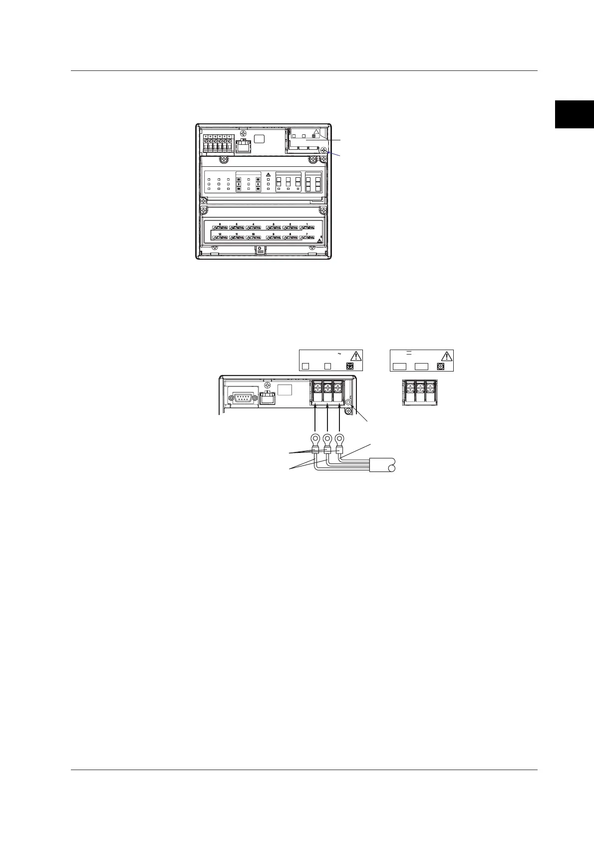
Power Terminal and Protective Ground Terminal Arrangement
Power terminals and protective ground terminal are arranged as shown in the figure
below.
Terminal cover screw
Power terminals / Protective ground terminal
Wiring Procedure
1. Turn OFF the power to the FX100, and open the cover (transparent) for the
power supply wires.
2. Connect the power cord and the protective ground cord to the power supply
terminals. Use crimp-on lugs with isolation sleeves (for 4-mm screws).
Power supply wires
Protective ground wire
100-240V AC
50/60Hz 35VAMAX
L N
Crimp-on lug with
isolation sleeve
Tightening torque for
cover screws: 0.6N•m
24V DC 17VA MAX
24V AC~50/60Hz 30VA MAX
L(+) N(-)
except for /P1 model for /P1 model
3. Close the cover (transparent) for the power supply wires and secure it in place
with screws.
2.5 Wiring the Power Supply

 Loading...


