AFNZPxxx– DUALACE2 NEW GENERATION – User Manual Page 113/169
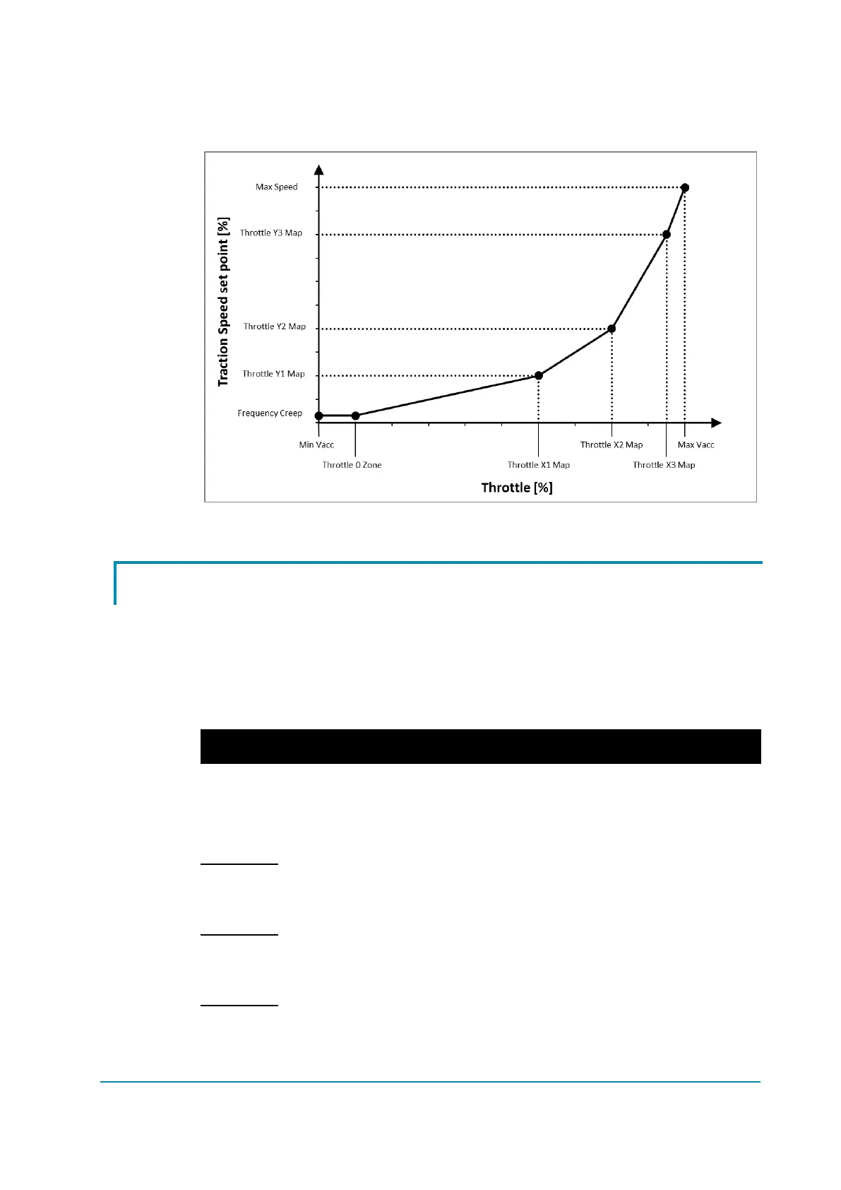
defines a dead zone close to the neutral position. For higher potentiometer
voltages, the speed set-point grows up as a polygonal chain. The following graph
better displays the throttle – speed relationship.
Throttle profile.
9.10 MC and EB modulation
The outputs dedicated to drive the main contactor and the electromechanical
brake are PWM-modulated in an open loop fashion (voltage controlled).
For both the outputs, dedicated parameters (under SET OPTIONS list) define the
pull-in duty-cycle and the retention one, the first applied in the first second of
actuation, the latter afterwards. The following table summarizes how parameters
effect such duty-cycles.
Example 1:
MC VOLTAGE = 100% Pull-in duty-cycle = 100%
MC VOLTAGE RED. = 80% Retention duty-cycle = 80% (100% x 80%).
Example 2:
MC VOLTAGE = 80% Pull-in duty-cycle = 80%
MC VOLTAGE RED. = 100% Retention duty-cycle = 80% (80% x 100%).
Example 3:
MC VOLTAGE = 80% Pull-in duty-cycle = 80%
MC VOLTAGE RED. = 80% Retention duty-cycle = 64% (80% x 80%).