Page 112/169 AFNZPxxx – DUALACE2 NEW GENERATION – User Manual
The profile is valid both for positive and negative angle values.
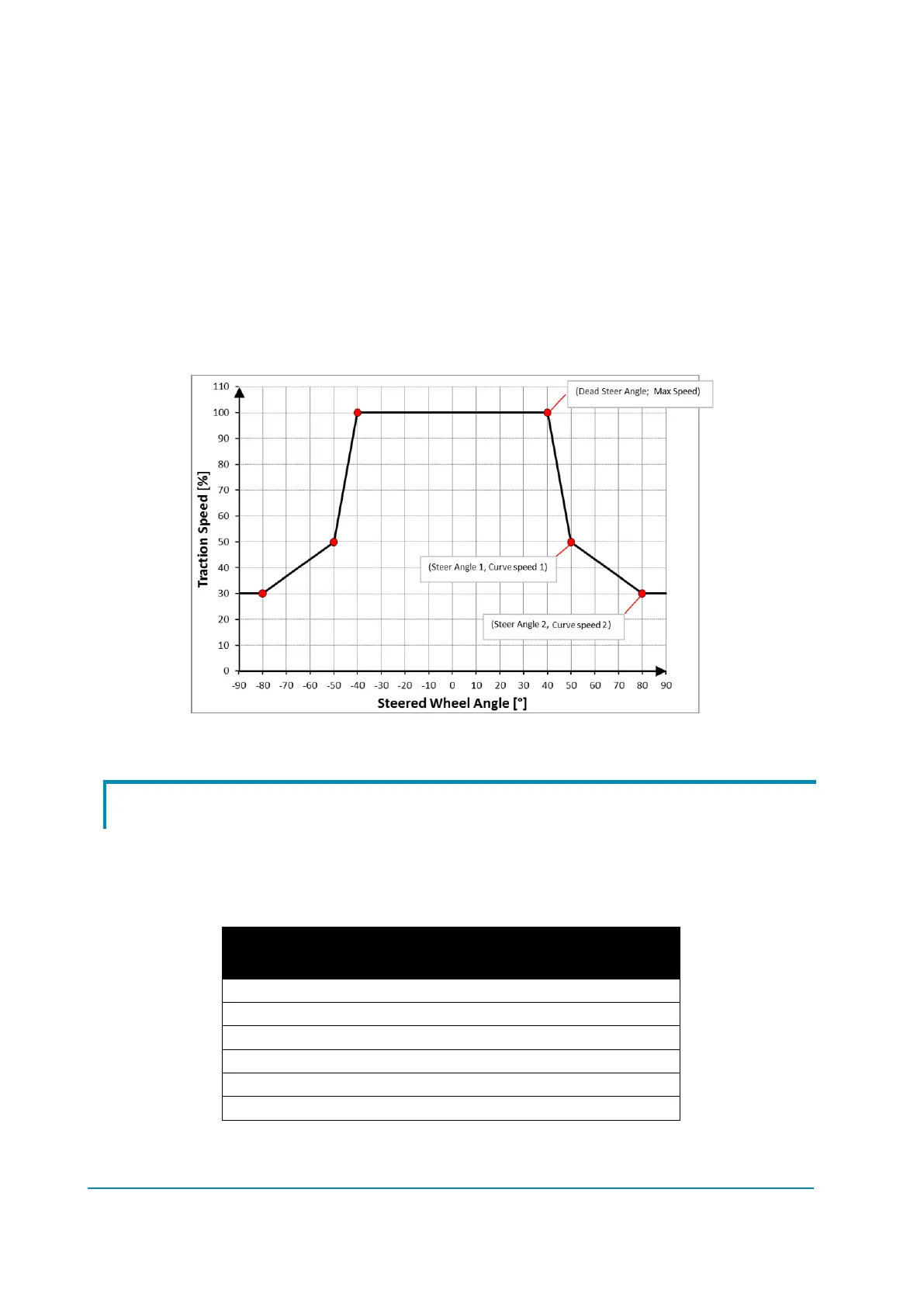
Example:
Three-wheel CB truck
Permitted steering-wheel angles = -90° ÷ 90°
CURVE SPEED 1 = 50%
CURVE SPEED 2 = 30%
STEER DEAD ANGLE = 40°
STEER ANGLE 1 = 50°
STEER ANGLE 2 = 80°
This set of parameters define the speed profile depicted in the graph below.
Steering curve.
9.9 Throttle profile
The controller performs the speed control along a non-linear function of the
accelerator position, so to provide a better resolution of the speed set-point at low
speed. The relationship between the throttle voltage and the speed set-point is
defined as a polygonal chain, as per the following table of points.
The speed remains at the FREQUENCY CREEP value as long as the voltage
from the accelerator potentiometer is below THROTTLE 0 ZONE. Basically this