Page 44/169 AFNZPxxx – DUALACE2 NEW GENERATION – User Manual
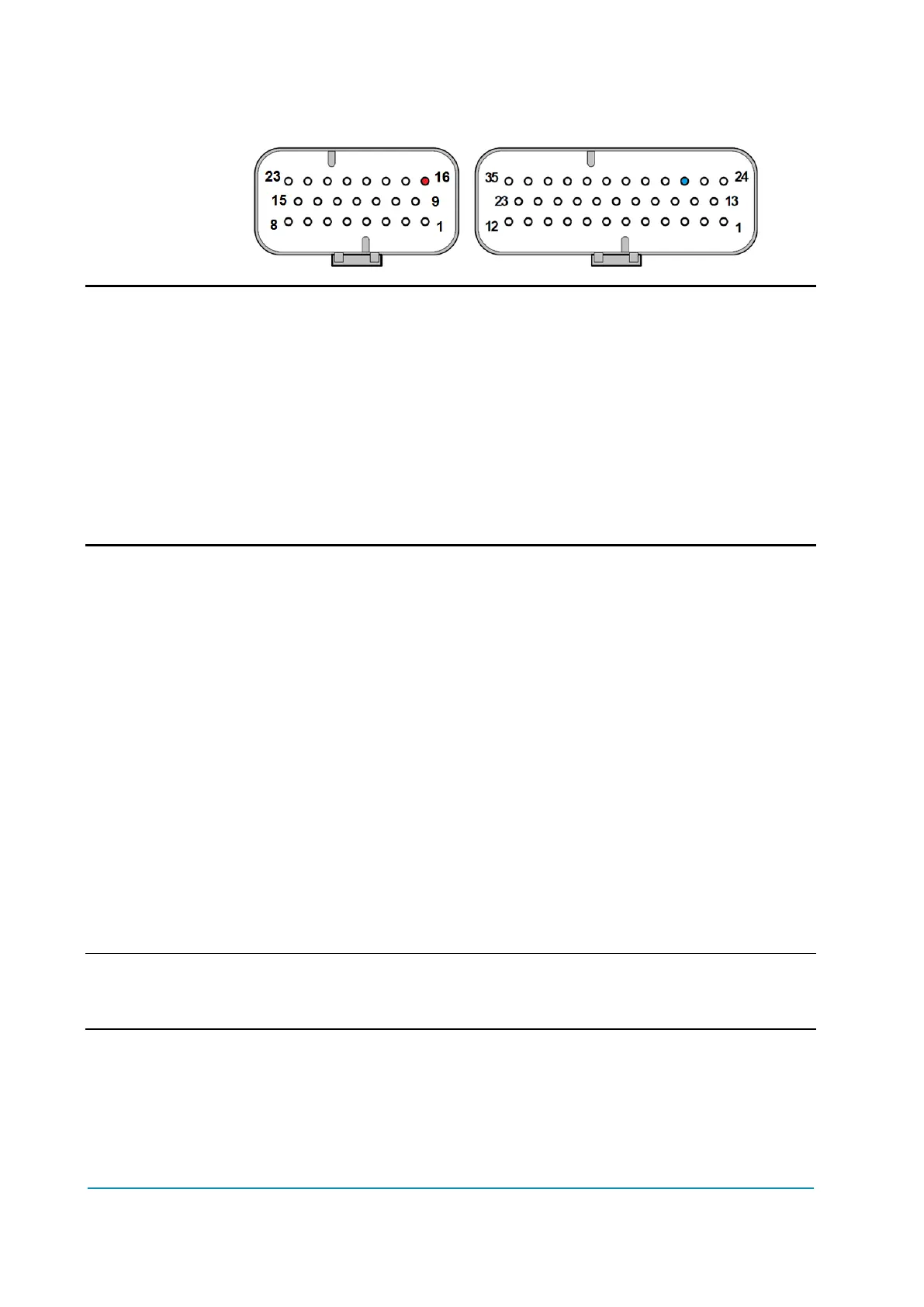
Connector position
Standard Premium
A16 A26
To protect the controller from overvoltage caused by an inductive load,
freewheeling diode to pin KEY A3 (A1) is built-in.
Please ensure that inductive loads are connected so that the paths through
the freewheeling diodes are always present; otherwise use external
freewheeling diodes.
Use of brushless fan or other loads with built-in capacitors may lead to
high inrush currents at turn-on, which may eventually bring to open-drain
overcurrent trips. Inrush current must be below the peak current.
4.4.6 EB outputs
Electromechanical brakes are operated through an open-drain PWM-voltage-
controlled outputs on pin NEB_R A28 (A18) and NEB_L A29 (A19). In order to
utilize the built-in freewheeling diodes, the coil must be supplied by pin PEB A27
(A17) (see chapter 3.1.1), which in turn is supplied by a high-side driver (see
paragraph 4.4.8).
In case the vehicle design does not allow the usage of the built-in freewheeling
diode, i.e. if the return path integrity cannot be guaranteed in all situations,
external freewheeling diodes must be applied over the inductive loads supplied
by the open drain outputs.
Output features
Up to 2.5 Arms continuous current (holding).
Up to 3 A peak (pulling) current for a maximum of 200 ms.
Individual hardware for detection of: shorted driver, open driver, open coil.
1 kHz PWM frequencies.
Configurable output voltage, by means of separate parameters for pulling
and holding stages.
PWM shall only be used for inductive loads such as relays, contactors, motor
brakes or hydraulic valves.
Protection
Protected against inductive discharge with internal freewheeling diode to pin PEB
A27 (A17) and ESD protected by suppressor device.
Not protected against reverse polarity of the battery. A way to avoid a failure
caused by the polarity inversion is to activate the contactor only when the voltage
over the DC-bus capacitors has reached the accepted pre charge level.