Page 48/169 AFNZPxxx – DUALACE2 NEW GENERATION – User Manual
Protection
PTH input is protected against short circuits to +B and ESD protected by
suppressor device. A low-pass filter attenuates the noise from the motor.
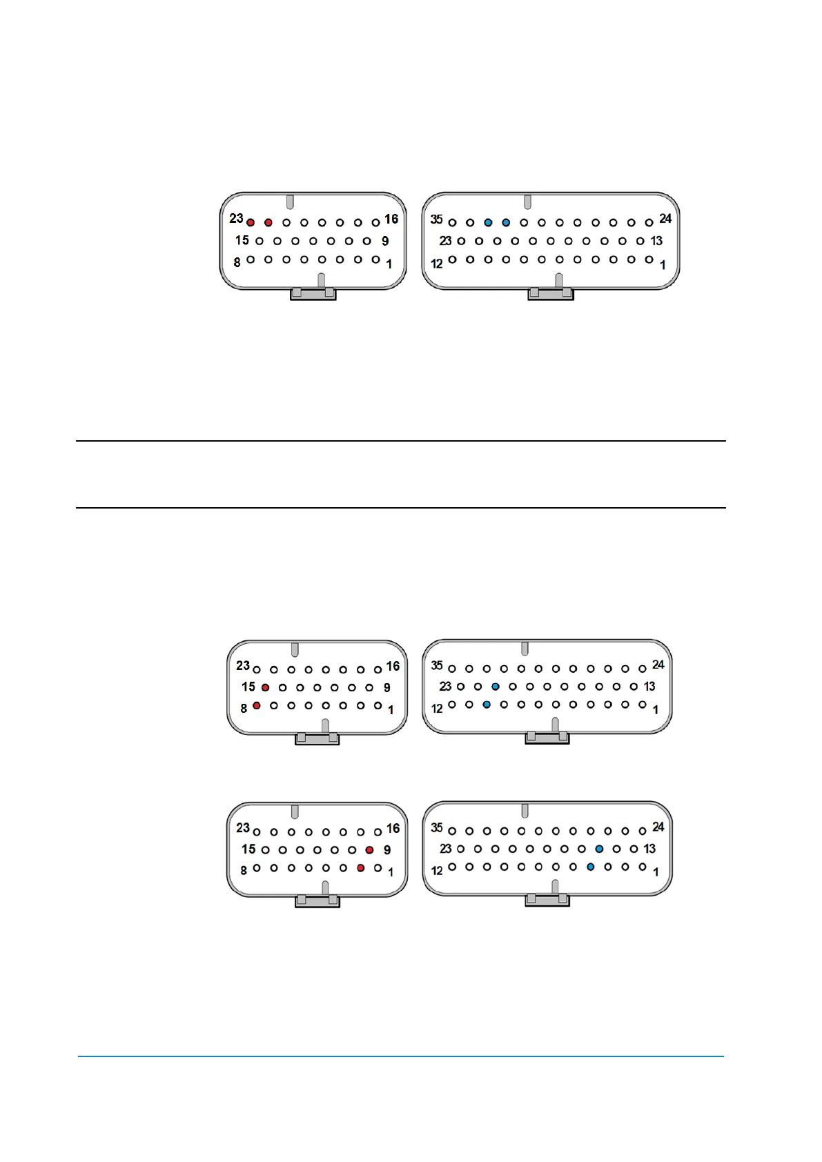
Connector position
Standard Premium
A22, A23 A32, A33
4.4.10 Sensor supply
Supplies for external motor-speed sensors are available between pin PENC_R
A10 (A8) and pin NENC_R A21 (A15) and between pin PENC_L A4 (A2) and pin
NENC_R A15 (A9).
Output voltage is configurable via hardware by internal jumper to +12V or +5V;
the maximum output current is 200 mA.
Actual values for “+12V” and “+5V” are respectively 12.1 V ± 0.5 V and
5 V ± 0.3 V.
Protection
Sensor supply has a current limiter at 200 mA and it is protected against
accidental connection to +B with a diode.
Connector position
Standard Premium
A8, A15 A10, A21
Standard Premium
A2, A9 A4, A15
4.4.11 CAN bus
CAN bus interface is available for communication with the controller, featuring:
Physical Interface according to ISO 11898-2.
Data rate can be 125, 250 or 500 kbit/s.
CAN driver is +5 V supplied and provides a rail to rail signal on the
differential output (CANH - CANL).
An internal 120 Ω termination resistor can be built-in.