AFNZPxxx– DUALACE2 NEW GENERATION – User Manual Page 55/169
Correct Layout:
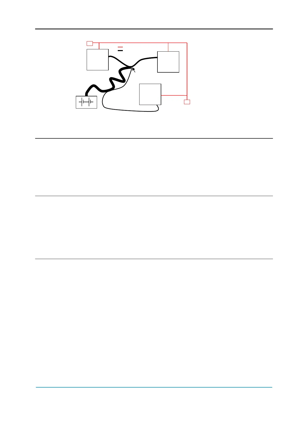
Note: Module 1 power ≈ Module 2 power > Module 3 power
In this case, the power cables of the two similar controllers must be as short as
possible. Of course also the diameter of the cables concurs in the voltage drops
described before (a greater diameter brings to a lower impedance), so in this last
example the cable between negative battery terminal and the center of the
ground connection (pointed by the arrow in the image) must be sized taking into
account both thermal and voltage drop problems and considering the current
drawn from the battery by the overall system.
The complexity of modern systems needs more and more data, signal and
information must flow from a node to another. CAN bus is the solution to different
problems that arise from this complexity.
- simple design (readily available, multi sourced components and tools)
- low costs (less and smaller cables)
- high reliability (fewer connections)
- ease of analysis (easy connection with a pc for sniffing the data being
transferred onto the bus).
5.2.5 Wirings: I/O connections
- After crimping the cable, verify that all strands are entrapped in the wire
barrel.
- Verify that all the crimped contacts are completely inserted on the connector
cavities.
- For information about pin assignment, see chapter 3.2.
- Very high currents may circulate between motor controller and battery. Even
if cables are dimensioned correctly, this may lead to a significant voltage
drop between motor controller B- terminal and negative terminal on the
battery. This means that there may be voltage differences between GND
references of different units in a control system. Therefore it is strongly
recommended to connect all wires of sensors supplied by the motor
controller directly to the intended I/O connector pins.
- Consider an alternative path for I/O cables that generates less noise (EMC).