Page 38/169 AFNZPxxx – DUALACE2 NEW GENERATION – User Manual
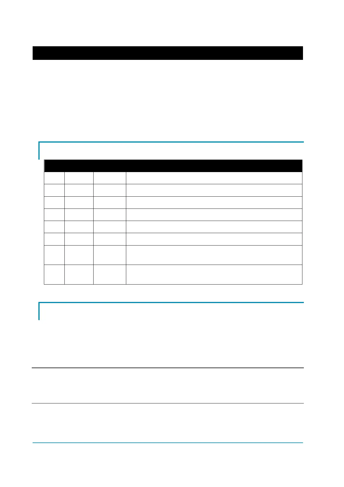
DUALBLE2 NEW GENERATION with Hall sensors
Third left-hand side Hall sensor.
Third right-hand side Hall sensor.
Negative supply for the right-hand side Hall sensors, the right-
hand side thermal sensor and potentiometers.
Not used: it can be unconnected.
Negative serial reception.
Positive serial transmission.
Negative serial transmission.
Negative console power supply.
Positive console power supply.
It must be connected to pin 8 for the Flash memory
programming.
It must be connected to pin 7 for the Flash memory
programming.
4.4 External devices
4.4.1 Key input
KEY input A3 (A1) is generally connected to the vehicle start key switch. It
supplies battery voltage to the logic circuitry and it also pre-charges the DC-link
capacitors at key-on, before main contactor closes. The KEY voltage is
monitored.
Note: external loads connected to the power terminal +B, such as proximity
switches, load the internal PTC resistor along the key input path, with the
consequence that the pre-charge voltage may be lower than expected.