Page 56/169 AFNZPxxx – DUALACE2 NEW GENERATION – User Manual
A cable connected to the wrong pin can lead to short circuits and failure;
so, before turning on the truck for the first time, verify with a multimeter the
continuity between the starting point and the end of a signal wire.
5.2.6 Motor feedback sensor
To minimize the possibility of electrical noise coupling into motor feedback sensor wires,
avoid routing cables next to conductors carrying high currents or high current pulses.
Noise immunity may also be improved by using twisted conductor cable for the motor
feedback sensor cables from motor to the motor controller.
Wiring of feedback sensor and the relationship between feedback sensor vs.
rotational direction depends upon feedback sensor installation in the motor.
Contact the motor manufacturer to get the correct wiring and relationship
between rotational direction and feedback sensor signals. Swapping the
channels from feedback sensor will lead to improper motor operation.
The motor feedback sensor may be ESD sensitive; see ESD related system
design suggestions in chapter 12.4.
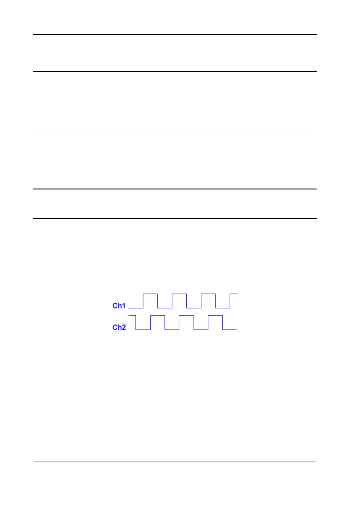
Incremental encoder speed signals
The incremental encoder speed sensor provides speed and direction feedback for the
motor controller. The standard speed encoder switches two open collector outputs to
produce two square wave signals phase shifted 90 º ±45 º (see Figure 16), with a
maximum frequency of 20 kHz. The sensor signals must have a minimum 6μs edge
separation.
The motor controller can be configured to accept different pulses/revolution.
Figure 16. Incremental speed encoder signals
The speed encoder sensor signals are connected to the Encoder CHA & CHB inputs
(chapter 4.4.4) and the sensor is supplied using sensor supply (see chapters 4.4.10).
Six-step (or UVW) encoder signals
The six-step encoder, for DC brushless motors, provides position, speed and direction
feedback for the motor controller. The six-step encoder switches three open collector
outputs to produce a three-phase square wave output for six-step commutation timing
(see Figure 17), phase shifted 120 º ±15 º, max 400 Hz. The motor controller can be
configured to operate DC brushless motors.