AFNZPxxx– DUALACE2 NEW GENERATION – User Manual Page 57/169
Figure 17. Six-step encoder signals
The six-step encoder sensor signals are connected to the SH1, SH2 and SH3 inputs
(chapter 4.2.6) and the sensor is supplied using sensor supply (see chapters 4.4.10).
Care must be taken to ensure that the six-step hall device matches the motor
controller sensor supply voltage
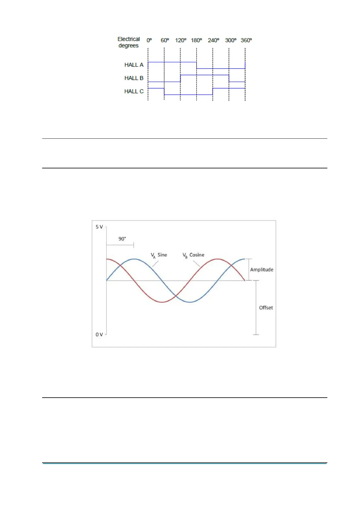
Sinusoidal Motor Speed Sensor Input
The sinusoidal sensor for synchronous motors provides position, speed and direction
feedback for the motor controller. The sinusoidal analog sensor produces a single-ended
two-phase sinusoidal wave output (see Figure 19).
Figure 19. Sinusoidal analog sensor signal
Connect the feedback sensor according to chapter 4.2.5.
Dynamic offset and gain adjustments (individual for each channel) are done in software
to compensate for minor changes in sensor characteristics.
It is suggested to share with Zapi technicians the specifications of the
adopted encoder in order to be sure about its full compatibility with the
Zapi controller
The number of pulses/rev can be properly set using the dedicated
parameters (see paragraph 8.2.7).