12 ZXP Series 7 Card Printer Service Manual P1036102-007
Theory of Operation
System-Level Electronics
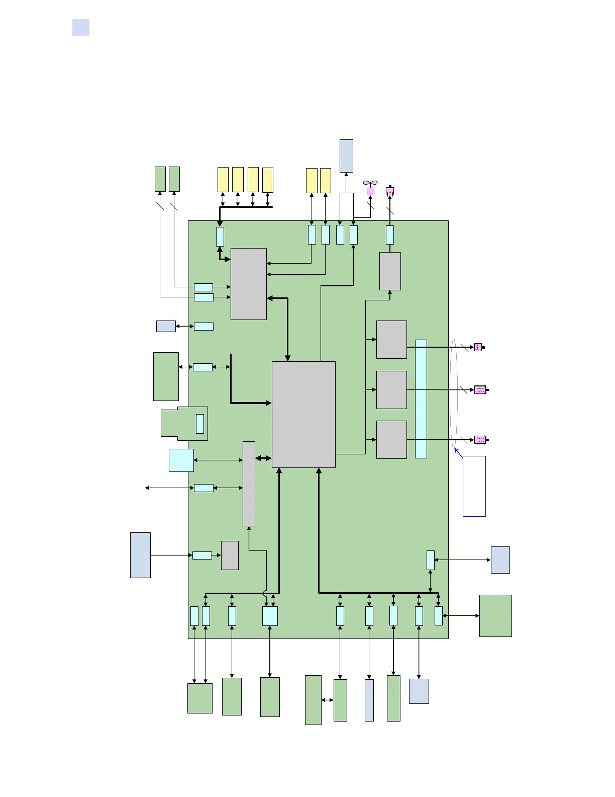
PCBA Block Diagram
Most of the circuitry in the printer is on the Main PCBA. Since the Main PCBA is not a
serviceable unit, there is no component level circuit analysis.
Main PCBA
MTR_CAM
4
A4983
MAIN
4
MTR_RIBS
MTR_RIBT
Gap
Sensor
Gap
Sensor
SEN_SENC
SEN_CAM
Gap
Sensor
Gap
Sensor
SEN_CSYN
SEN_DOOP
Ethernet
Daughter
Board
(PCBA_ENET)
J2
CA_OCP
Barcode
Reader
(BARCD)
SmartCard
Authentication
(Contact SmartCard
for User Auth)
(PCBA_USRAUTH)
CA_UCONN
CA_MAB
CA_LAM_CTL
CA_OPSC
CA_OPMAG
CA_FDFLIP_PWR
CA_FDFLIP_CTL
J28
J27
J50
J51
J22
J7
J10
J21
J30
J19
J20
J16
A3966
2
BEMF Circuit
2
UHF/Felica
CA_UHF-FELICA
J1
J26
USB Logic
CPU Subsystem
(FPGA, DDR, Flash,
clock buffering, I2C mux, etc.)
DC-DC
Power
Conversion
A3979
J8
MCB Motor Driver Interfaces
MCB Sensor Interfaces
Sensor Interface
(tri-color sensor circuit,
74HC14's for digital sensor inputs,
A2D for analog inputs)
USB Interfaces
Remote Board Interfaces
External Module Interfaces
Debug Interfaces
CA_BARCD
CA_USRAUTH
J24
Flipper
Module
PCBA
(PCBA_FLIP)
These motors each plug into
a C/A (CA_MTR_MCB) that
connects to J16 here.
Media Auth PCBA
(PCBA_MAB)
Media Auth
Coupler PCBA
(PCBA_CPLR_MAB)
Laminator (LAM)
OCP Support PCBA
(PCBA_OCP)
200W Power Supply
(PWR_SUP)
CA_DCPWR
CA_SEN_MCB
SmartCard PCBA
(PCBA_OPSC)
Mag PCBA
(PCBA_OPMAG)
(PH_PWR)
(PH_DATA)
CA_PH
Print Head Interface
J5
J29
Print Head
(PH)
CA_CPLR_MAB
Gap
Sensor
SEN_TENC
J9
Gap
Sensor
SEN_EXIT
J11
J52
IP/EP Diagnostic Board
(PCBA_DIAG_IF,
P1043417-01)
USB_PERIPH_PC
USB_HOST_PANEL
FAN_PH
2
J35
Tri-Color
Emitter
Tri-Color
Detector
SEN_RIBA
SEN_RIBB
Thermistor
J36
J34
2
5
CA_THERM
 Loading...
