EasyManuals Logo

Zebra ZXP 7 series Service Manual

Zebra ZXP 7 series
384 pages
To Next Page IconTo Next Page
To Previous Page IconTo Previous Page
Page #363 background imageLoading...
Page #363 background image
P1036102-007 ZXP Series 7 Card Printer Service Manual 357
Replacement Procedures for the High-Capacity Output Hopper
Procedures: PCBA
Installation
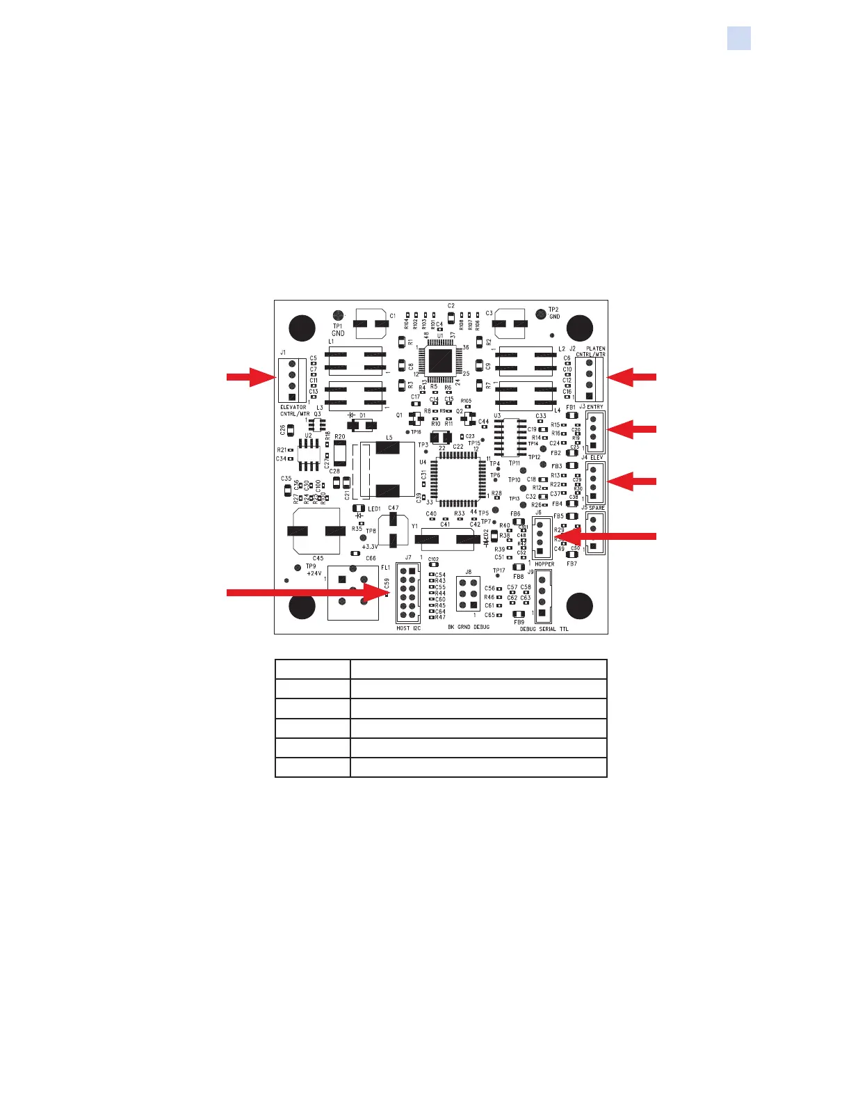
Step 1. Connect the platen motor control/power cable to J2, and elevator motor
control/power to J1 on the PCBA.
Step 2. Connect the lift cam sensor control to J4 on the PCBA.
Step 3. Connect the hopper present sensor to J6 on the PCBA.
Step 4. Connect the stacker entry sensor to J3 on the PCBA.
Step 5. Connect the high-capacity output hopper control cable to J7 on the PCBA.
J3
J2J1
J7
J4
J6
J1 Elevator Motor Control/Power
J2 Platen Motor Control/Power
J3 Stacker Entry Sensor
J4 Lift Cam Sensor
J6 Hopper Present Sensor
J7 Hopper Control/Power

Table of Contents

Other manuals for Zebra ZXP 7 series

Questions and Answers:

Question and Answer IconNeed help?

Do you have a question about the Zebra ZXP 7 series and is the answer not in the manual?

Zebra ZXP 7 series Specifications

General IconGeneral
Print Resolution300 dpi
ConnectivityUSB 2.0, Ethernet
Memory64 MB standard
Print TechnologyDye-sublimation thermal transfer
Card Capacity200 cards input hopper, 100 cards output hopper
Card SizesCR-80 ISO 7810, 2.12" (54 mm) x 3.38" (86 mm)
Power Requirements100-240 VAC, 50-60 Hz

Related product manuals