Parameters 127
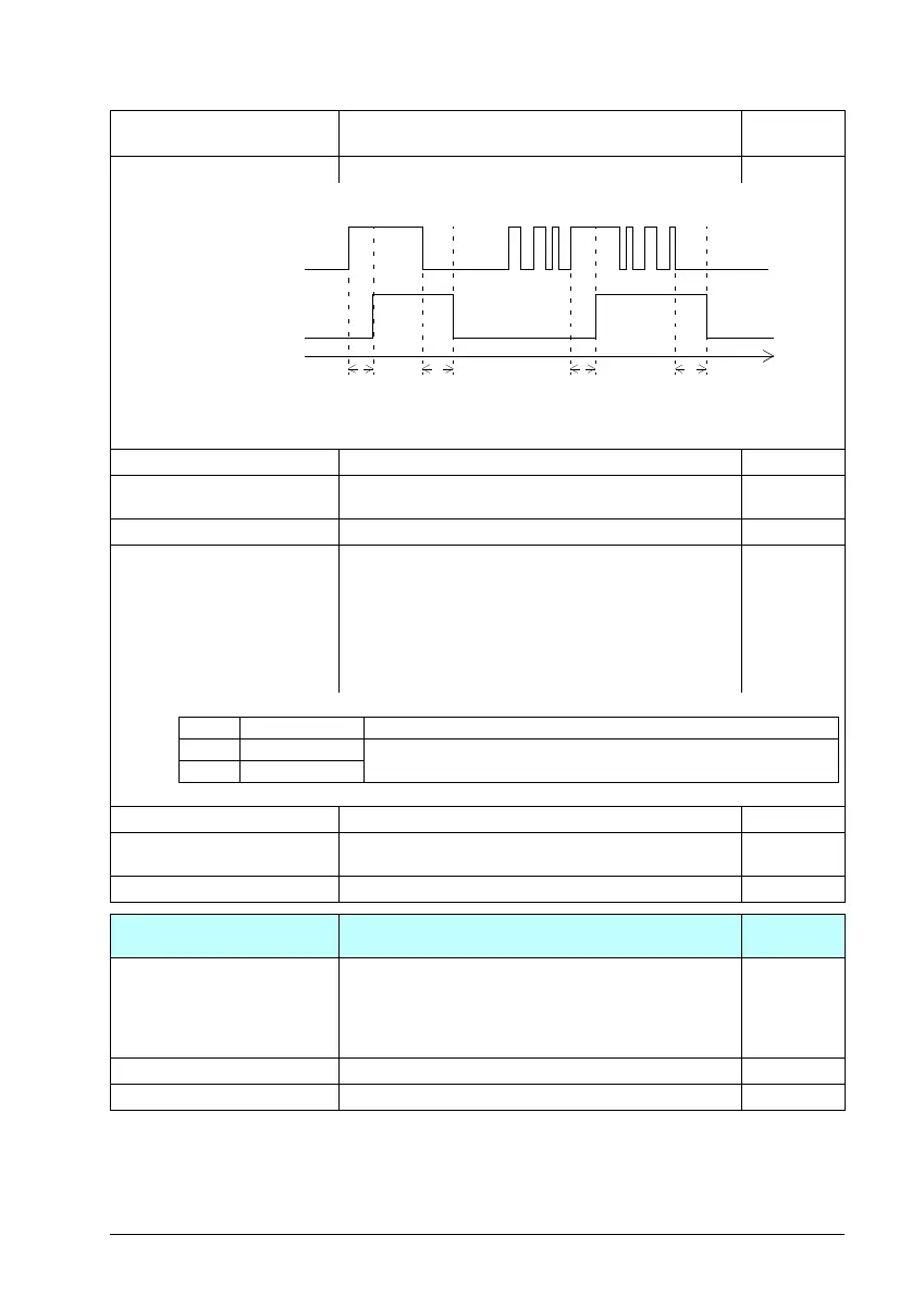
10.25 RO1 ON delay Defines the activation delay for relay output RO1. 0.0 -
t
On
= 10.25 RO1 ON delay
t
Off
= 10.26 RO1 OFF delay
0.0 … 3000.0 s Activation delay for RO1. 10 = 1 -
10.26 RO1 OFF delay Defines the deactivation delay for relay output RO1. See
parameter 10.25 RO1 ON delay.
0.0 -
0.0 … 3000.0 s Deactivation delay for RO1. 10 = 1 -
10.99 RO/DIO control word Storage parameter for controlling the relay outputs eg.
through the embedded fieldbus interface. To control the
relay outputs (RO) of the drive, send a control word with
the bit assignments shown below as Modbus I/O data. Set
the target selection parameter of that particular data
(58.101…58.114) to RO/DIO control word. In the source
selection parameter of the desired output, select the
appropriate bit of this word.
0000h
0000h…FFFFh RO control word. 1 = 1
10.101 RO1 toggle counter Displays the number of times relay output RO1 has
changed states.
-
0…4294967000 State change count. 1 = 1
11
11 Standard DIO, FI, FO
Configuration of the digital inputs/outputs (DIO) for use as
digital inputs,
11.02 DIO delayed status Displays the delayed status of digital outputs DO1. This
word is updated only after activation/deactivation delays
(if any are specified).
Example: 0001 = DO1 is on.
This parameter is read-only.
-
DO1 Delayed status of digital output 1. 1 = 1
0000b…0001b Status of digital outputs. 1 = 1
No. Name/Value Description Default
FbEq 16
1
0
1
0
t
On
t
Off
t
On
t
Off
Status of selected
source
RO status
Time
Bit Name Description
0 RO1 Source bits for relay outputs (see parameter 10.24).
8DO1
ACS180 FW.book Page 127 Tuesday, March 9, 2021 2:25 PM