Program features 81
Outputs of the brake control logic
The mechanical brake is controlled by bit 0 of parameter 44.01 Brake control status.
This bit should be selected as the source of a relay output (or a digital output) which is
then wired to the brake actuator through a relay. See the wiring example on page 84.
The brake control logic, in various states, will request the drive control logic to hold
the motor, or ramp down the speed. These requests are visible in parameter 44.01
Brake control status.
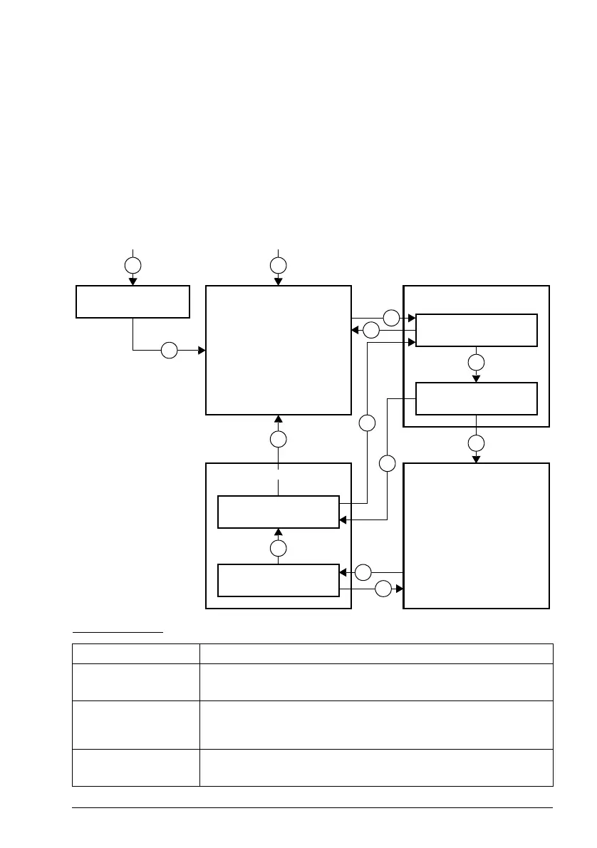
Brake state diagram
State descriptions
State name Description
BRAKE DISABLED Brake control is disabled (parameter 44.06 Brake control enable = 0, and 44.01
Brake control status b4 = 0). The open signal is active (44.01 Brake control
status b0 = 1).
BRAKE OPENING: Brake has been requested to open. (44.01 Brake control status b2 = 1). Open
signal has been activated (44.01 Brake control status b0 is set). The load is
held in place by the speed control of the drive until 44.08 Brake open delay
elapses.
BRAKE OPEN The brake is open (44.01 Brake control status b0 = 1). Hold request is removed
(44.01 Brake control status b2
=
0), and the drive is allowed to follow the
reference.
BRAKE CLOSING
DELAY
BRAKE CLOSING WAIT
BRAKE DISABLED BRAKE OPENING
BRAKE OPENING WAIT
BRAKE OPENING
DELAY
BRAKE CLOSED
BRAKE OPENBRAKE CLOSING
(from any state)
1
(from any state)
2
3
4
5
6
6
6
7
8
9
3
10
ACS180 FW.book Page 81 Tuesday, March 9, 2021 2:25 PM