Actual signals and parameters 271
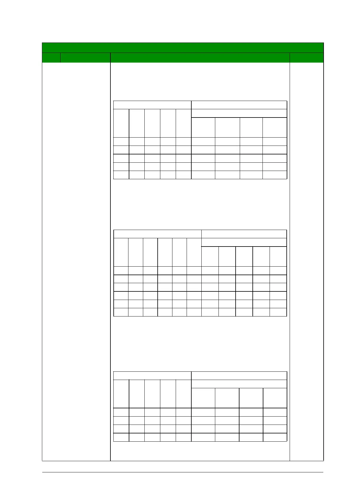
The table below shows the PFC motor assignments for
some typical settings in the relay output parameters
(1401…1403 and 1410), where the settings are either = 31
(PFC), or = X (anything but 31), and where the Autochange
function is disabled (8118 AUTOCHNG INTERV = 0).
If five auxiliary motors are needed, use the transistor output
(parameter 1805 DO SIGNAL) as an additional relay output.
In relay order, TO is set between RO 1 and RO 2. The table
below shows the PFC motor assignments for some typical
settings when TO is in use.
The table below shows the PFC motor assignments for
some typical settings in the relay output parameters
(1401…1403 and 1410), where the settings are either = 31
(PFC), or = X (anything but 31), and where the Autochange
function is enabled (8118 AUTOCHNG INTERV > 0).
All parameters
No. Name/Value Description Def/FbEq
Parameter setting Relay assignment
1
4
0
1
1
4
0
2
1
4
0
3
1
4
1
0
8
1
1
7
Autochange disabled
RO 1 RO 2 RO 3 RO 4
31 X X X 1 Aux. X X X
31 31 X X 2 Aux. Aux. X X
31 31 31 X 3 Aux. Aux. Aux. X
X 31 31 X 2 X Aux. Aux. X
31 31 X X 1* Aux. Aux. X X
* = One additional relay output for the PFC that is in use.
One motor is in “sleep” when the other is rotating.
Parameter setting Relay assignment
1
4
0
1
1
8
0
5
1
4
0
2
1
4
0
3
1
4
1
0
8
1
1
7
Autochange disabled
RO 1 TO RO 2 RO 3 RO 4
31 X X X X 1 Aux. X X X X
31 31 X X X 2 Aux. Aux. X. X X
31 31 31 X X 3 Aux. Aux. Aux. X X
31 31 31 31 X 4 Aux. Aux. Aux. Aux. X
31 31 31 31 31 5 Aux. Aux. Aux. Aux. Aux.
31 31 31 31 X 4* Aux. Aux. Aux. Aux. X
* = One additional relay output for the PFC that is in use.
One motor is in “sleep” when the other is rotating.
Parameter setting Relay assignment
1
4
0
1
1
4
0
2
1
4
0
3
1
4
1
0
8
1
1
7
Autochange enabled
RO 1 RO 2 RO 3 RO 4
31 31 X X 1 PFC PFC X X
31 31 31 X 2 PFC PFC PFC X
X 31 31 X 1 X PFC PFC X
31 31 X X 0** PFC PFC X X
** = No auxiliary motors, but the Autochange function is in
use. Working as a standard PID-control.