Program features 97
For amplitude logger 2, the user can select a signal to be sampled at 200 ms
intervals, and specify a value that corresponds to 100%. The collected samples are
sorted into 10 read-only parameters according to their amplitude.
• Parameter 1 shows the share of samples that have fallen in range 0... 10% of
the reference value during the time that the logging has been active.
• Parameter 2 shows that share of samples that have fallen in range 10...20% of
the reference value during the time that the logging has been active
•etc.
You can view this graphically with the assistant panel or the Drive composer PC tool.
Amplitude logger 1 is fixed to monitor motor current, and cannot be reset. With
amplitude logger 1, 100% corresponds to the maximum output current of the drive
(I
max
). The measured current is logged continuously. The distribution of samples is
shown by parameters 36.20…36.29.
Parameters and diagnostics
Parameters: group 36 Load analyzer.
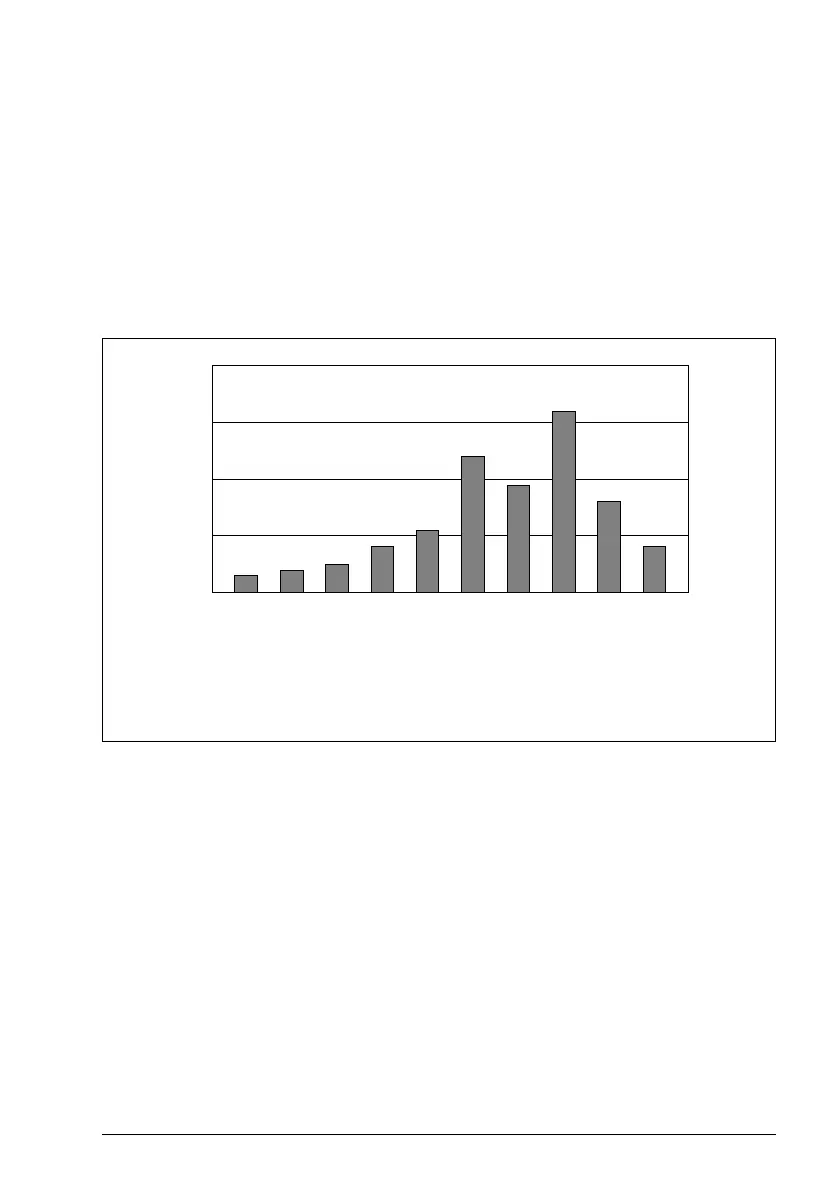
share of all samples
0…10%
10…20%
20…30%
30…40%
40…50%
50…60%
60…70%
70…80%
80…90%
>90%
Amplitude ranges
(parameters 36.40…36.49)

 Loading...


