EN 15
Additional information
For more information, see DriveConfig User’s Guide [3AFE68910897 (English)].
No. Name Information
1NOM
FREQ Hz
Defines the motor nominal frequency (see the motor rating plate).
2 SILENT Defines the drive switching frequency. Note: The higher the frequency the more electromagnetic
noise and the shorter the allowed motor cable length to comply with the European EMC
regulations. See Technical data on page 22. Note: The switching frequency adapts to the
ACS55 temperature.
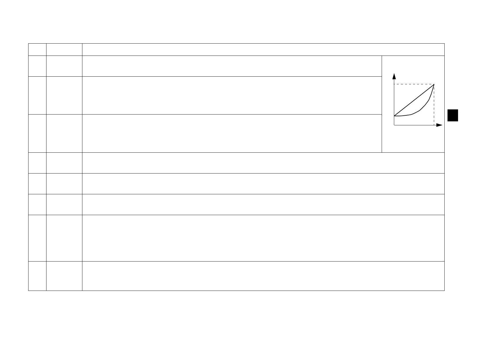
3 LOAD Optimises the output voltage and frequency characteristics according to the load. Select P&F for
the squared torque (e.g. pumps and fans) and CT for the constant torque loads (e.g. conveyors).
ACS55 automatically boosts the starting voltage 10% to compensate the motor losses and to
increase the starting torque.
4 JOG Hz Defines the jogging frequency. Activate the jogging function on by connecting 12…24 VDC to digital input 3 ("JOG").
(Drive accelerates or decelerates to the jogging frequency, and keeps it until the input is switched off.)
5 RELAY Selects the drive state the normally open contact of the relay output indicates. FLT = Fault. Contact is opened while
at a fault state or at a power off state. RUN = Running. Contact is closed while running.
6AI
OFFSET
Activates a living zero supervision for the analogue input. 4 mA (2 V) = ACS55 trips on a fault if the value drops
below the limit. See section Speed controlling on page 20 for information on analogue input scaling.
7AUTO-
RESET
Activates the automatic reset function for the following faults: Undervoltage, overvoltage, analogue input loss.
ON = ACS55 will try to reset automatically three seconds after a fault trip. Maximum number of resets is ten in three
minutes. If exceeded, ACS55 stops and will not attempt a new reset. See also Status indications and fault tracing on
page 21.
Warning! If the start signal is on, the motor will be started after a reset. Make sure that this will not cause danger.
8 HI FREQ Defines the maximum output frequency. OFF: Max. frequency = value defined by the NOM FREQ HZ switch. ON:
Max. frequency = value defined by the NOM FREQ HZ switch + value of HI FREQ potentiometer. See Control
potentiometers on page 16.

 Loading...


