4 Repair
4.7.1. Replacement gearbox axis 1
3653HAC026876-001 Revision: F
© Copyright 2007-2010 ABB. All rights reserved.
Refitting
The procedure below details how to remove the gearbox axis 1.
Action Note
1. If the base not already is resting on the
support base and gear, axis 1, this should be
done first.
Mounting of the support base and gear,
axis 1 is detailed in section Removal on
page 363.
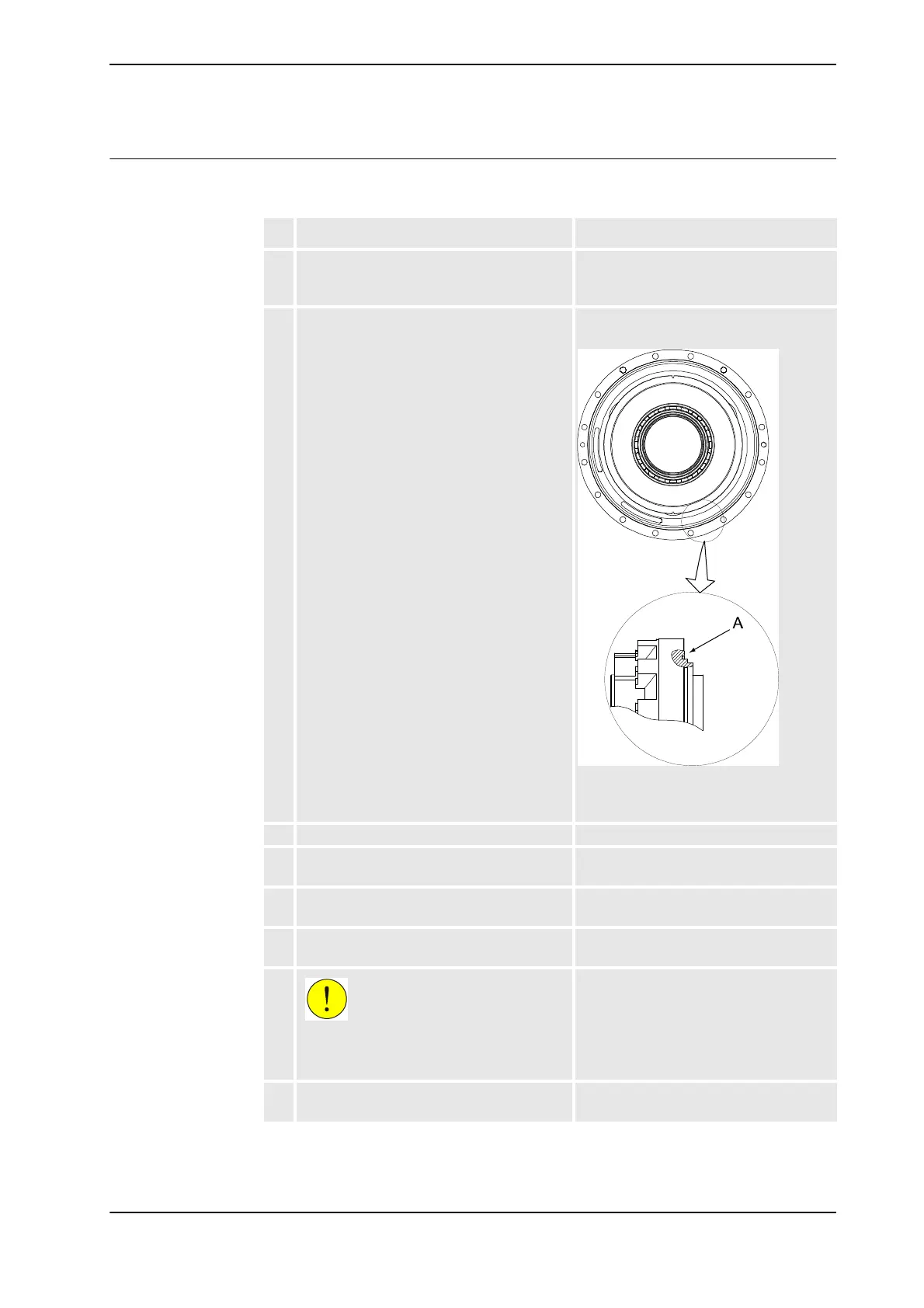
2. Make sure the o-ring is fitted to the gearbox
as shown in the figure to the right.
Lightly lubricate the o-ring with grease.
Art. no. is specified in Required
equipment on page 362.
xx0200000055
• A : O-ring (Gearbox shown from
the side)
3. Fit the three o-rings (23x3.6). Use some grease to attach them.
4. Refit the protection pipe axis 1 in the center
of gearbox 1 with its attachment screws.
Shown in the figure Location of gearbox
axis 1 on page 361.
5. Fit two lifting eyes on each side of the
gearbox and secure it with a roundsling.
Art. no. is specified in Required
equipment on page 362.
6. Fit two guide pins in two of the attachment
holes, parallel to each other.
7.
CAUTION!
The gearbox weighs 108 kg! All lifting
equipment used must be sized accordingly!
8. Lift the gearbox on to the guide pins and
lower it carefully to its mounting position.
Continued
Continues on next page