7 Reference information
7.8. Dismounting and mounting tool 3HAC028920-001
4153HAC026876-001 Revision: F
© Copyright 2007-2010 ABB. All rights reserved.
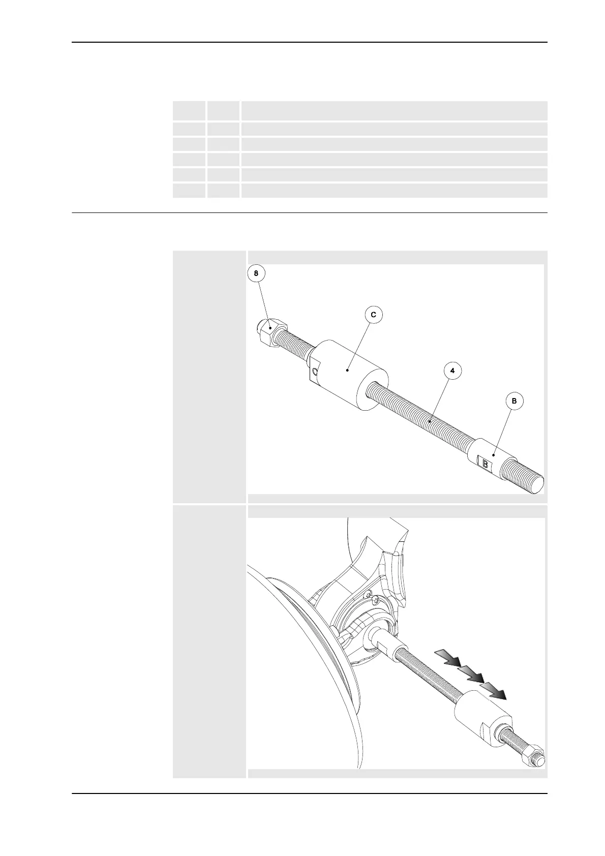
Removal front shaft design 1 and 2
The following configuration is used for removal of the front shaft Design 1 and 2. In the
figure only Design 1 is shown.
9 E Press tool D=85
10 K Press tool D=100
11 G Press tool D=110
12 J Press tool D=90
13 H Press tool D=62
Item Mark Description
Configuration:
•8
•C
•4
•B
xx0900000026
1) Assemble the
adapter B into
the shaft.
2) Assemble the
threaded bar,
M16 into the
adapter.
3) Assemble the
Slide hammer /
Distance on to
the threaded bar,
M16.
4) Assemble the
nut M16.
xx0900000027
Continued
Continues on next page