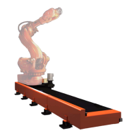
Mechanical installation
Foundation
3HEA 800 970-001 Rev. D, Mars 2006 2-5
Installation and operation
2 Mechanical installation
2.1 Foundation
2.1.1 Robustness
The foundation must withstand the static loads caused by the weight of the
equipment and the dynamic loads generated by the movement of the carriage and
manipulator.
2.1.2 Incline
The foundation must be designed so that the track motion can be mounted without
the incline exceeding 0.5 mm/m in the direction of travel and 0.1 mm/m across the
direction of travel.
2.1.3 Static loads
The table shows the static loads that the foundation must be able to bear.
2.1.4 Dynamic loads
The dynamic loads from the movement of the track motion and manipulator can
change direction independent of each other. If loads are added to each other, the
foundation must be able to bear these combined loads.
The maximum dynamic loads for the track motion are:
• (Weight, carriage + Weight, manipulator + Weight, extra load) × Acceleration
See the robot documentation with regard to dynamic loads for the robot.
Load Value
Distributed load, stand 270 kg/m
Movable, in the direction of travel
Manipulator 2400 kg
Carriage 600 kg
Adaptor, IRB 4400 160 kg
Permitted extra load
IRB 4400 100 kg
IRB 6600 400 kg
The track motion should not be used so that the maximum loads from the robot and conveyor
are added to each other. If, for example, the carriage is used at maximum speed in one
direction, the robot arm should be at a standstill or moving in the opposite direction.

 Loading...