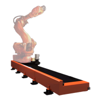
Mechanical installation
Securing the stand to the foundation
2-22 3HEA 800 970-001 Rev. D, Mars 2006
Installation and operation
2.3.7 Securing the stand to the foundation
Follow the instructions below to secure the stand to the foundation.
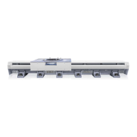
2.3.8 Fitting the cover plates
Follow the instructions below to fit the cover plates.
Note!
Make sure that there is free space (1,200 mm) for installation/dismantling of the switching
point J1. See "Connection point J1" on page 2 - 29.
Action
1. Check that none of the leveling bolts on the track motion's ground plates are hanging
in the air or that the distance between the leveling bolts and the top edge of the ground
plates is at least 10 mm.
Adjust if necessary according to "Adjusting the level" on page 2 - 10.
2. Move the carriage manually and check using the spirit level along the entire travel
length, both in the direction of travel and across it.
The carriage can be moved manually if 24 VDC is connected to the motor; see
page 1- 4.
Adjust if necessary according to "Adjusting the level" on page 2 - 10.
3. Drill holes for the mounting bolts through the ground plates' mounting holes
(max. Ø24).
The holes vary depending on the chosen mounting method, see "Recommendations
for mounting" on page 2 - 6
4. Secure the track motion to the foundation using an appropriate anchoring method.
The anchoring method must be adapted to the foundation and the dynamic loads that
the track motion generates, see "Foundation" on page 2 - 5 and "Recommendations
for mounting" on page 2 - 6.
5. Continue with "Fitting the cover plates" on page 2 - 22.
Action Info/Illustration
1. Fit cover plates over all joints.
2. Fit end plates on the track motion's ends.
3. Mount the calibration sign according to
position 3.
1
2
2
3
 Loading...