LOCAL OPERATION ANALOG MODULATION
3-92
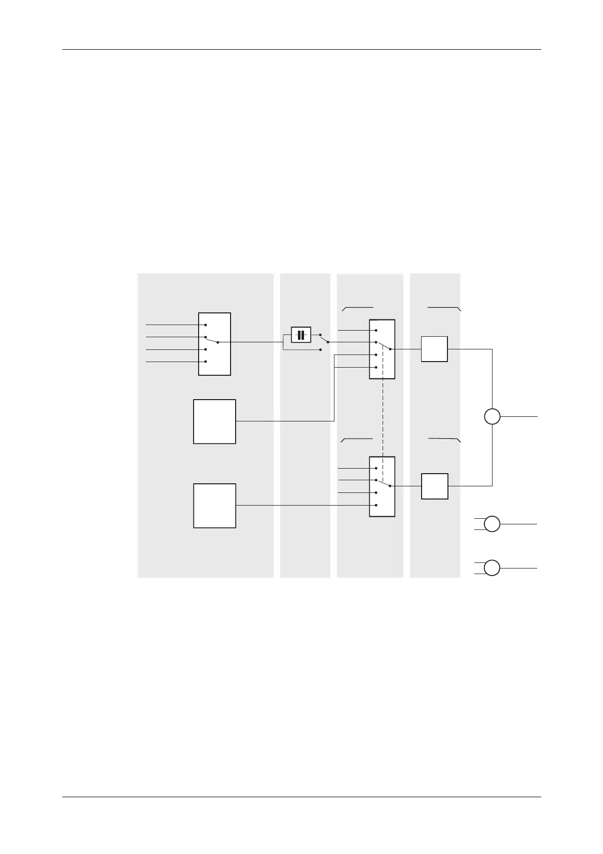
Path set-up
Before setting up the analog internal/external sources and modulation paths, you may find it
helpful to look at Fig. 3-68.
It shows the various parameters that may be set up, and the menus in which you can find them, for
amplitude modulation. The FM and ΦM modulation diagrams would be very similar, and so are
not repeated.
While this diagram does not set out to portray accurately the instrument’s hardware, it does
represent the effect of the menus on the instrument’s operation.
AM1 INTERNAL SOURCE
AM2 INTERNAL SOURCE
EXTERNAL SOURCE
¡Depth
¡Coupling
AC
DC
¡Depth
¡Ext
¡100 k 1 VRMS
¡100 k 1 VPK
¡Int1
¡Int1+Int2
¡Off
¡50 1 VRMS
¡50 1 VPK
AM1 + AM2
FM1 + FM2
M1 + M2
AM sub-menu
or
Int/Ext Source sub-menu
AM sub-menu
or
Ext Source
sub-menu
Modulation
mode
AM sub-menu
C5210
¡Freq
¡Shape
¡Freq
¡Shape
¡Phase
¡Sensitivity
AM PATH 2
AM PATH 1
¡Ext
¡Int
¡Int1+Int2
¡Off
Fig. 3-68 Path set-up
Parameters that can be adjusted are shown as (for example) Freq.
Apart from selecting the signal path(s), all parameters can be adjusted from the AM, FM and ΦM
sub-menus on pages 3-93 to 3-99. They can also be adjusted from the internal source sub-menus
on pages 3-102 to 3-105.
 Loading...
