INSTALLATION
2-6
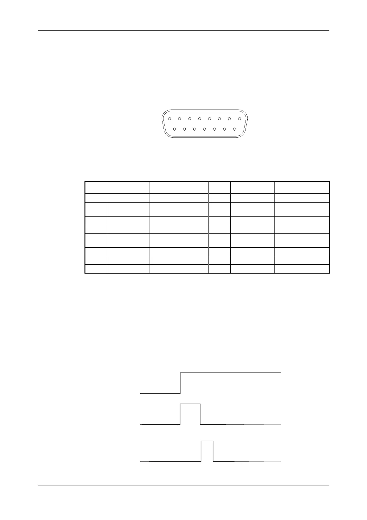
Auxiliary port connector
The 15-way female D-type AUXILIARY PORT connector is shown in Fig. 2-3. This provides:
inputs and outputs for RF A/B level and burst operation; outputs of markers 1, 2 and 3 from an
ARB waveform; list mode trigger input and ‘in transit’ and start marker out. Levels are TTL
(HCT). A breakout box (part no. 82542) is available; this converts the D-type connector to BNC
male sockets. Breakout box markings are shown in capital letters in the table below.
C5206
1
8
9
15
Fig. 2-3 15-way AUXILIARY PORT connector (looking onto rear panel)
The pin-outs for the AUXILIARY PORT connector and breakout box are as follows:
Contact Function Breakout box Contact Function Breakout box
1 Burst out BURST OUT 9 Ground Ground
2 Not connected AUXILIARY 1 10 Marker 1 out
(power ramp)
MARKER OUTPUTS 1
3 List start mkr out OUTPUTS MARKER 11 Burst gate in BURST IN
4 Marker 2 out (A/B) MARKER OUTPUTS 2 12 Not connected AUXILIARY 2
5 A/B burst atten
control in
BURST A/B 13 Marker 3 out MARKER OUTPUTS 3
6 List ‘in transit’ out OUTPUTS BLANK 14 Not connected AUXILIARY 3
7 ARB trigger in ARB TRIG IN 15 List trigger in AUX TRIG IN
8 Not connected AUXILIARY 4
Note: pin 11 (Burst gate in) is connected in parallel internally with rear-panel BNC connector
BURST GATE IN.
List mode triggering
The IN TRANSIT output shows that the instrument is changing to the next entry in the list. When
IN TRANSIT goes low, the instrument has stabilized at the list entry. START MARKER shows
that the instrument has reached the starting point in the list. IN TRANSIT and START MARKER
appear whether the list is triggered internally or externally.
You can also trigger a list by using the rear-panel TRIGGER IN BNC connector. +ve trigger is
the default, but you can also select −ve trigger.
EXT TRIGGER
IN TRANSIT
START MARKER
C5781