OPERATIONAL VERIFICATION TESTING
6-23
Differential IQ outputs (instruments fitted with
Option 009)
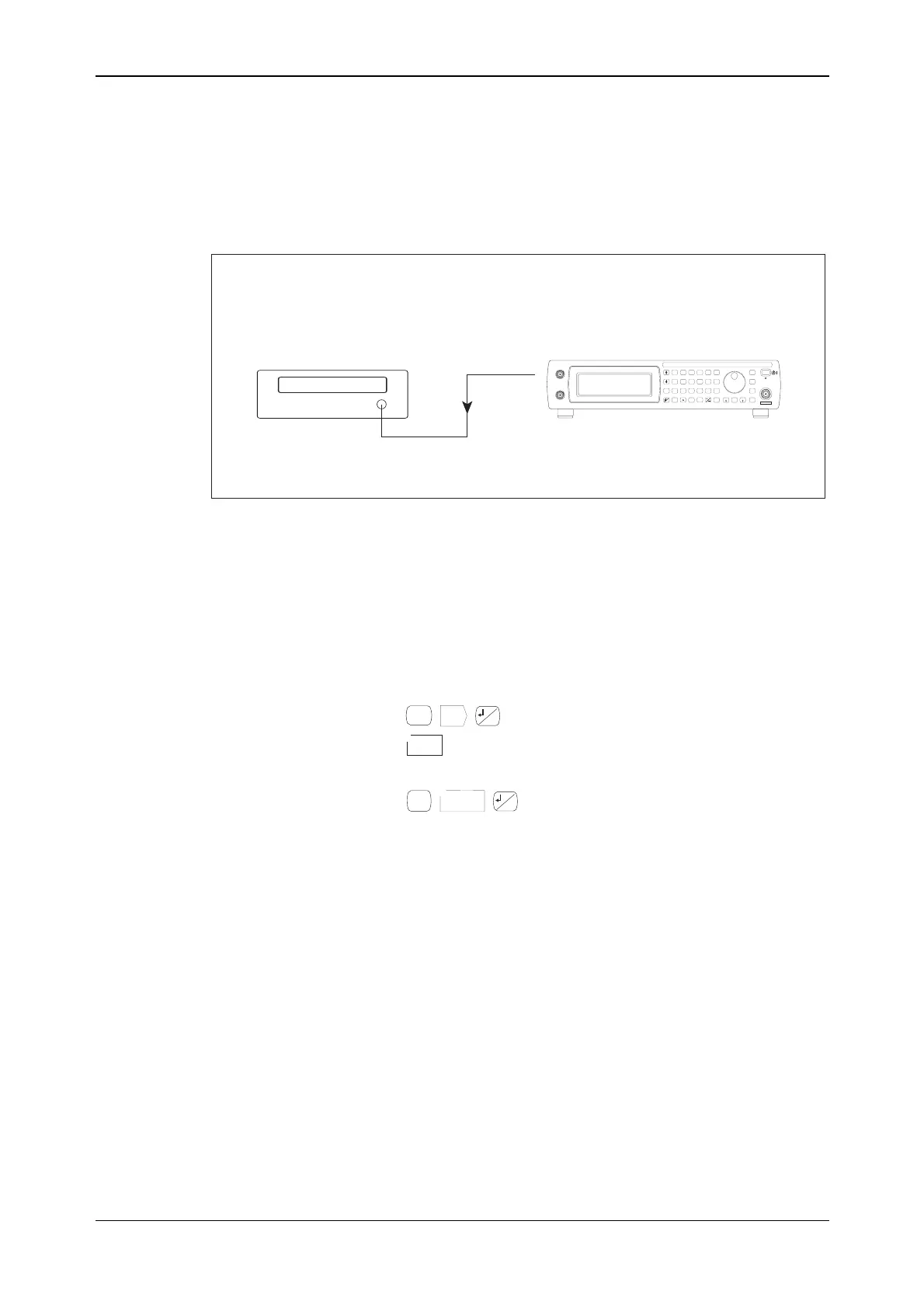
To test the performance of the I, Q, I and Q outputs, it is necessary to generate a 20 kHz test tone
on the I and Q outputs using ®.
C5683
UUT
Digital multimeter
V INPUT
I, Q, or OUTPUTS
(Rear panel)
IQ
SIG
GEN
IQ
MOD
ANALOG
MOD
RECALL
SAVE
UTIL
<TAB>
...
SWEEP
GHz
MHz
kHz
Hz
rad
s
ms
%
V
mV
mV
dB
KNOB/
STEP
ERROR
STATUS
SOURCE
ON/OFF
RF OUTPUT
50W
MOD
ON/OFF
RF
ON/OFF
x10
7
8
9
6
5
4
1
0
.
2
3
10
¸
EXT I
EXT AM
EXT Q
EXT FM
LOCAL
ENTER
50 /
100k
W
W
50 /
100k
W
W
REVERSEPOWER
50WMAX
Fig. 6-14 Differential IQ outputs test setup
Bias voltage accuracy
1 Connect the test equipment as shown in Fig. 6-14, with the cable connected to the I output.
2 On the UUT set:
SIG
GEN
IQ
...
...
<Self-Cal>
Start
Cal
0
Ensure that the IQ cal has successfully completed.
IQ
MOD
Diff IQ
3
...
<Bias> I Bias 3 [V]
3 Measure the voltage on the DMM against the limits shown in Table 6-8.
4 On the UUT set:
I Bias −3 [V]
5 Measure the voltage on the DMM against the limits shown in Table 6-8.

 Loading...