INSTALLATION
2-9
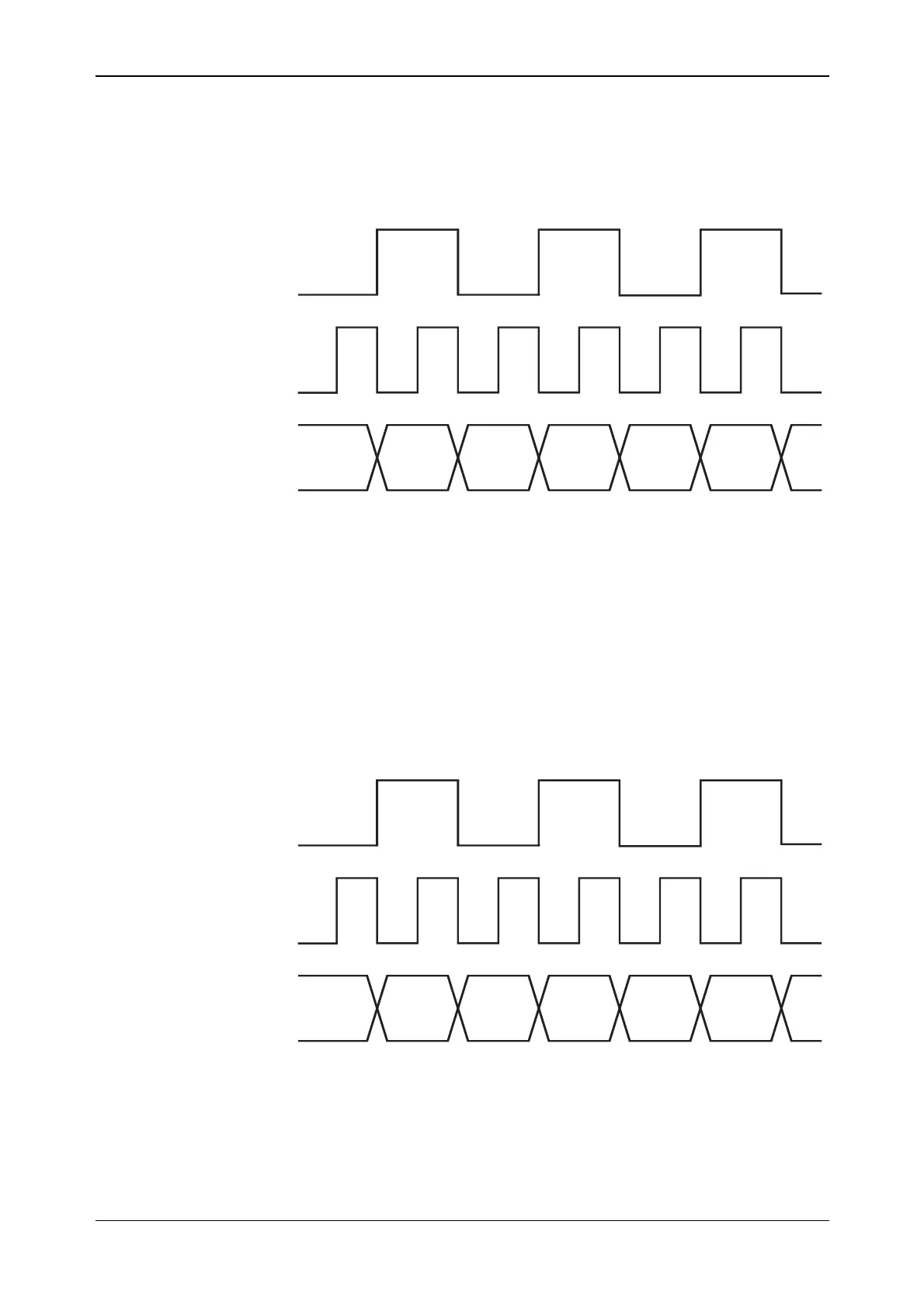
LVDS data used as IQ input
In this mode, data is fed to the LVDS interface using all 16 LVDS data lines. The LVDS
IQSELECT_OUT signal determines whether the data is I or Q (0=Q and 1=I). The CLK_OUT
signal runs at twice the I/Q sample rate.
IQSELECT_OUT
CLK_OUT
I data I data I data
Q data Q data
IQ Data input
D0–D15
C5728
CLK_OUT and IQSELECT_OUT are outputs on the LVDS. Data in is latched on the rising edge
of CLK_OUT. Alternatively, you can provide the clock using CLK_IN and select using
IQSELECT_IN — see CLK_OUT sync section on page 2-11.
LVDS data used as IQ output
In this mode, data is fed out of the LVDS interface using all 16 LVDS data lines. This is identical
to the previous mode except that the data direction is out. The LVDS IQSELECT_OUT signal
determines whether the data is I or Q (0=Q and 1=I). The CLK_OUT signal runs at twice the I/Q
sample rate.
IQSELECT_OUT
CLK_OUT
I data I data I data
Q data Q data
IQ Data output
D0–D15
C5729
CLK_OUT and IQSELECT_OUT are outputs on the LVDS. Data out is valid on the rising edge
of CLK_OUT.