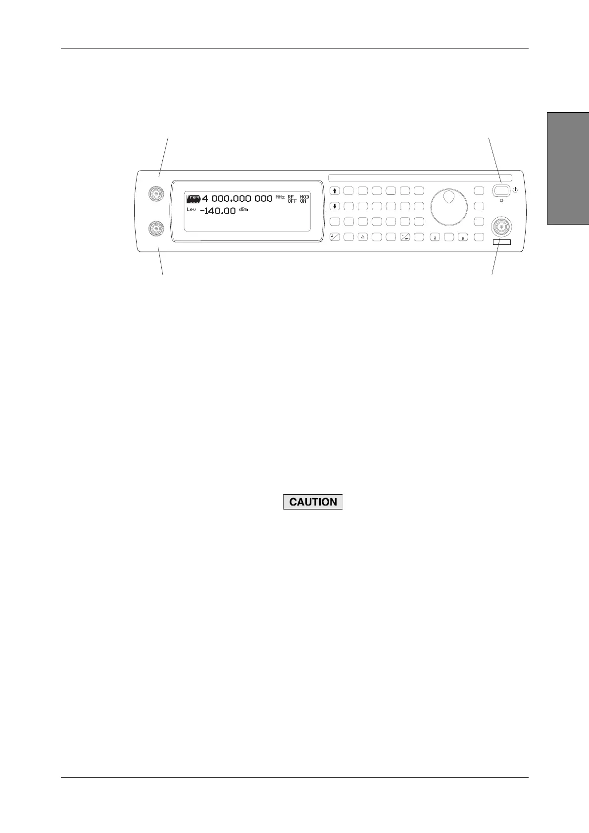
LOCAL OPERATION CONTROLS AND CONNECTORS
3-5
Introduction
Front-panel connectors and standby/on switch
Front-panel connectors and the standby/on switch are shown in Fig. 3-1 below.
C5187
SIG
GEN
IQ
MOD
ANALOG
MOD
RECALL
SAVE
UTIL
<TAB>
...
SWEEP
GHz
MHz
kHz
Hz
rad
s
ms
%
V
mV
V
dB
KNOB
STEP
ERROR
STATUS
SOURCE
ON/OFF
RF OUTPUT
50
MOD
ON/OFF
RF
ON/OFF
x10
7
8
9
6
5
4
1
0
.
2
3
10
EXT I
EXT AM
EXT Q
EXT FM
LOCAL
ENTER
50 /
100k
50 /
100k
REVERSE POWER
50W MAX
2
4
3
1
Fig. 3-1 Front panel
1 Standby/on switch Switches the instrument between the on and standby
modes, using a press on, press off action. To prevent
accidental operation, this switch has a built-in time delay of
about half a second before it is recognized.
The adjacent LED is amber during standby, showing that
power is applied to the crystal oscillator. The LED turns
green when the instrument is fully powered up.
Use the power supply switch on the rear panel (page 3-9)
to
isolate the instrument from AC line power.
2 RF OUTPUT
50 Ω N-type socket.
3412, 3413, 3414 are protected against the application of
reverse power of up to 50 W (to 3 GHz) or 25 W (to 4 GHz)
from a 50 Ω source. Protection remains active when the
AC line power is removed from the instrument.
3416 has no reverse power protection.
Maximum reverse power for 3416 is 0.5 W.
Option 007 locates this socket on the rear panel.
3 EXT Q/EXT FM Q input or external frequency modulation input (1 V rms or
1 V pk-pk). BNC socket, selectable 50 Ω/100 kΩ.
Q/FM OUT
Option 007 only. 50 Ω BNC socket, 1 V RMS: outputs the
Q signal from the ARB or the output of the FM source.
4 EXT I/EXT AM I input or external amplitude modulation input (1 V rms or
1 V pk-pk). BNC socket, selectable 50 Ω/100 kΩ.
I/AM OUT
Option 007 only. 50 Ω BNC socket, 1 V RMS: outputs the I
signal from the ARB or the output of the AM source.