LOCAL OPERATION MODULATION
3-33
Modulation
Modulation summary
• You configure the instrument for IQ or analog modulation by pressing the
IQ
MOD
or
ANALOG
MOD
key to
view the relevant modulation mode screen.
• You set up the type of modulation (‘modulation mode’) using the modulation mode screen.
The main screen then displays function labels that reflect your choice of modulation.
• You set up the individual paths using the function labels.
Possible combinations of modulation
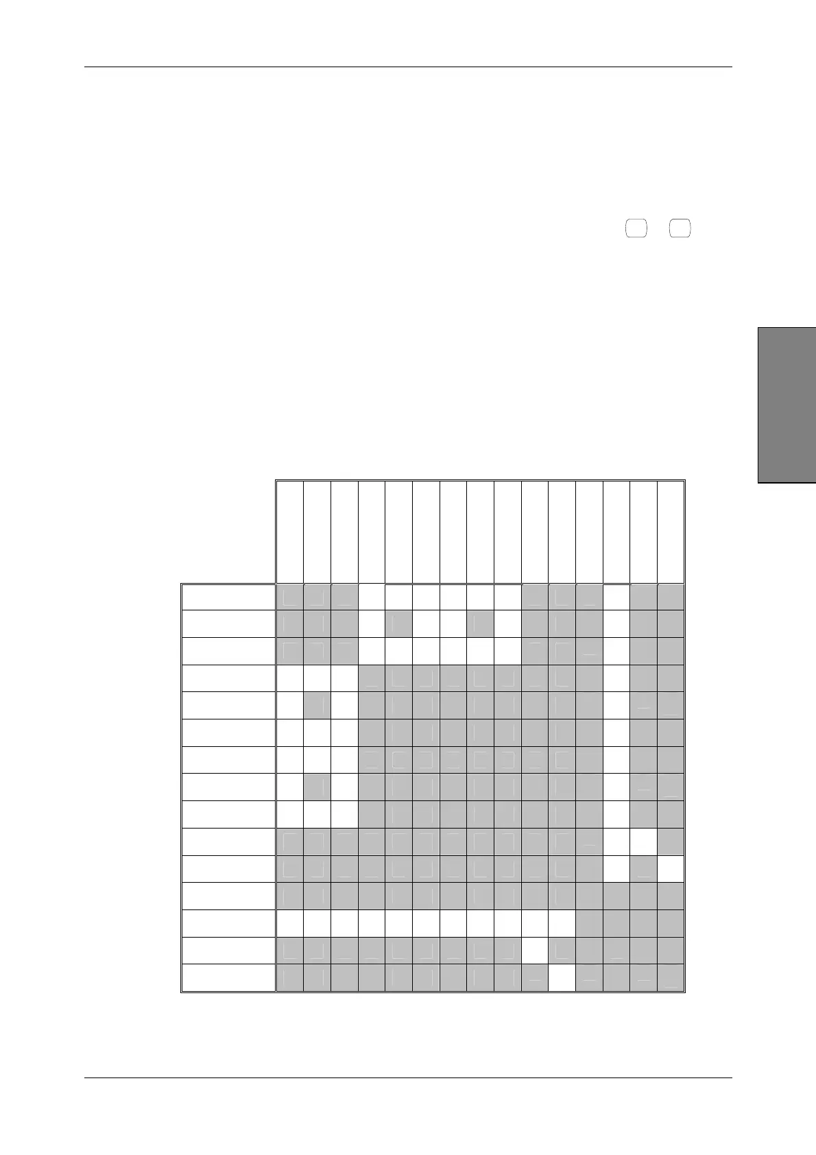
Table 3-1 shows the possible combinations of modulation. The types of modulation available
depend on the options fitted to your instrument, so some of these modulation types may not be
available.
Table 3-1 Combinations of modulation
Int AM1
Int (AM1+AM2)
Ext AM1
Int FM1
Int (FM1+FM2)
Ext FM1
Int ΦM1
Int (ΦM1+ΦM2)
Ext ΦM1
Internal IQ
External IQ
Differential IQ
Pulse
Int Burst
Ext Burst
Int AM1
√ √ √ √ √ √
√
Int (AM1+AM2)
√
√ √
√
√
Ext AM1
√ √ √ √ √ √
√
Int FM1
√ √ √
√
Int (FM1+FM2)
√
√
√
Ext FM1
√ √ √
√
Int ΦM1
√ √ √
√
Int (ΦM1+ΦM2)
√
√
√
Ext ΦM1
√ √ √
√
Internal IQ
√ √
External IQ
√
√
Differential IQ
Pulse
√ √ √ √ √ √ √ √ √ √ √
Int Burst
√
Ext Burst
√
√ Allowed combination