INSTALLATION
2-11
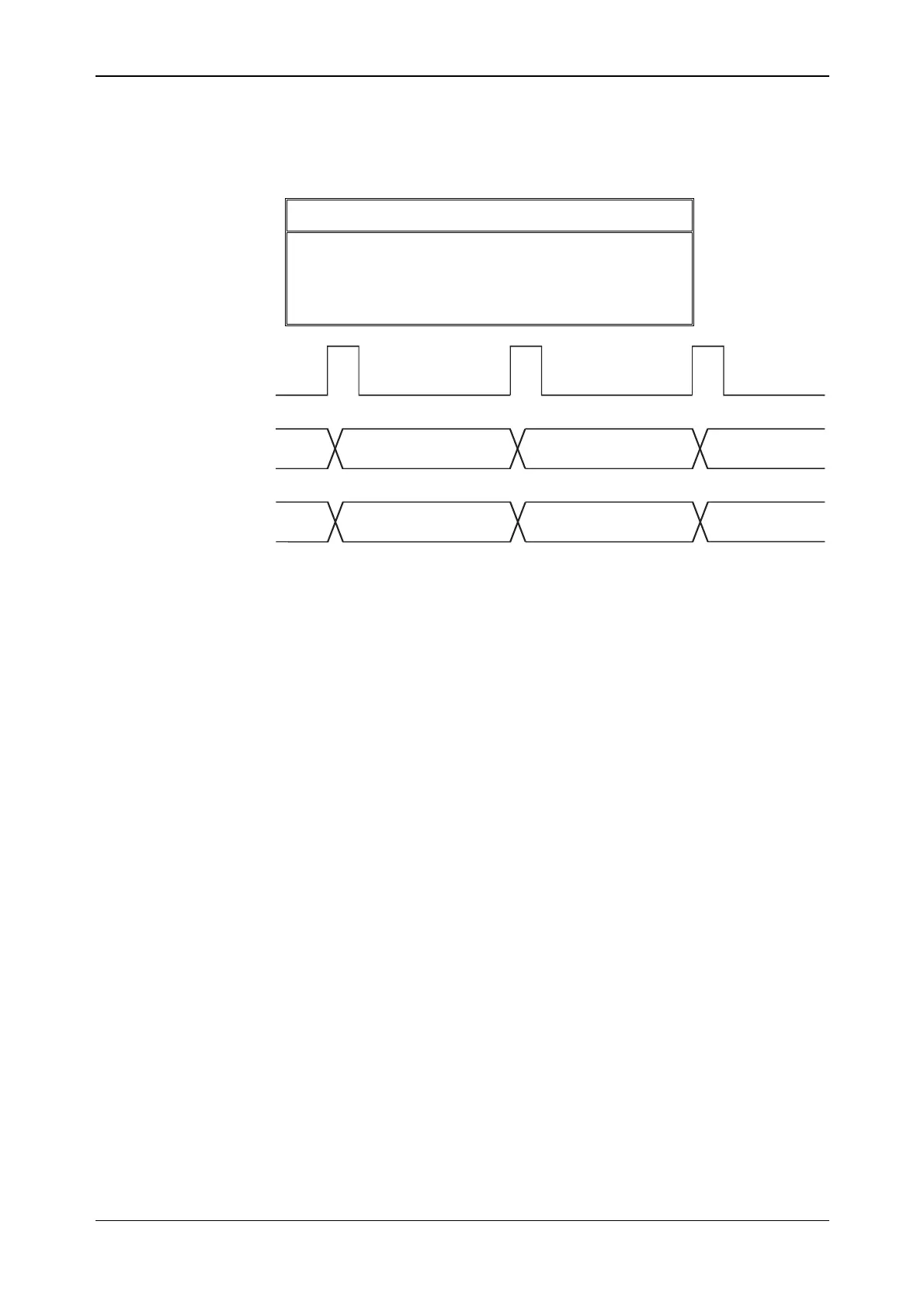
Example 2
Hop address is generated by the internal counter and appears as an output on the LVDS. The first
four entries in the lookup table as before are:
Hop Address RF offset frequency
0 0 MHz
1 10 MHz
2
−30 MHz
3 50 MHz
MARKER3
HOP_ADDR
(from counter)
2
3
0 MHz 10 MHz
-30 MHz
1
0
RF frequency
offset
C5687
Note: Because the values that appear on the LVDS hop address lines are from the internal
counter, they seem to be out of step with respect to the RF frequency offset. This is because the
value from the counter is latched on the rising edge of Marker 3, but the counter itself is also
incremented on the same rising edge. Therefore the hop address output will be one step ahead of
the RF frequency offset.
CLK_OUT sync
Although all the timing of the LVDS interface is based around CLK_OUT, you also can provide
an input clock. This is fed into the CLK_IN input on the LVDS connector. The LVDS interface
does not use CLK_IN for its timing but there is the facility to synchronize CLK_OUT to CLK_IN.
Once synchronized, the two clocks remain in phase provided that the following conditions are met:
• The 3410 Series instrument and the source are running from the same 10 MHz standard, and
• All sample rates between the instrument and the source are the same.
If I/Q data is being fed into the LVDS connector then it is important that IQSELECT between the
instrument and the source are also in synchronization. In this mode, you must provide
IQSELECT_IN as well as CLK_IN before they can be synchronized. As before, the instrument
does not use CLK_IN or IQSELECT_IN but merely synchronizes CLK_OUT and
IQSELECT_OUT to these signals.


 To Next Page