LOCAL OPERATION RF LEVEL
SIG
GEN
B5196
...
B5195
3-30
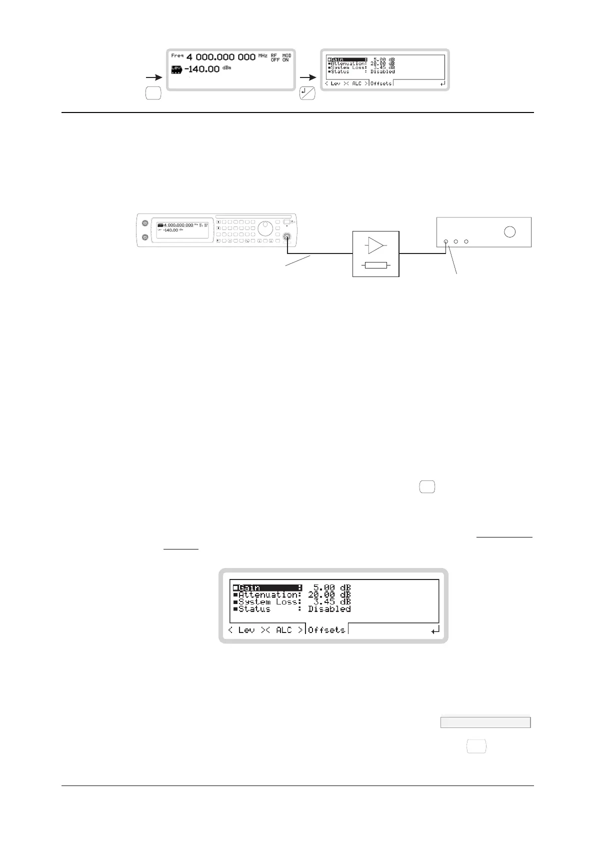
RF level menu — <Offsets>
From this menu, you can offset the RF output to compensate for the loss or gain resulting from an
external device or cabling connected between the instrument and the device under test (DUT)
(Fig. 3-23).
C5197
DUT
System loss
(cabling, terminations)
RF level:
the value you enter
is the level you want
to see here
Gain/
attenuation
SIG
GEN
SWEEP
UTIL
SAVE
RECALL
<TAB>
...
MOD
MODE
GHz
MHz
kHz
Hz
rad
s
ms
%
V
mV
V
dB
KNOB/
STEP
ERROR
STATUS
SOURCE
ON/OFF
RF OUTPUT
50
MOD
ON/OFF
RF
ON/OFF
x10
7
8
9
6
5
4
1
0
.
2
3
10
I
EXT AM
Q
EXT FM
LOCAL
ENTER
50 /
100k
50 /
100k
REVERSEPOWER
50WMAX
Fig. 3-23 RF level offsets
You set up the instrument so that:
• The gain or attenuation value is that of the external device and/or cabling.
• The RF level displayed is the level that you want at the DUT
The instrument automatically adjusts the signal level at its RF output to compensate for the
external device and to ensure that the correct level is presented to the DUT.
RF level
1 From the RF level menu of Fig. 3-21, touch <Offsets> or press
<TAB>
to display the RF offset
screen (Fig. 3-24).
2 Set gain, attenuation and system loss as required.
3 Finally, set the instrument’s RF level (page 3-24) to the level that you require at the input of
the DUT.
B5195
Fig. 3-24 RF level offset
Gain POW:OFFS page 4-150
Enter the gain of the external device (a positive value only, or 0), terminating with
Hz
rad
dB
.