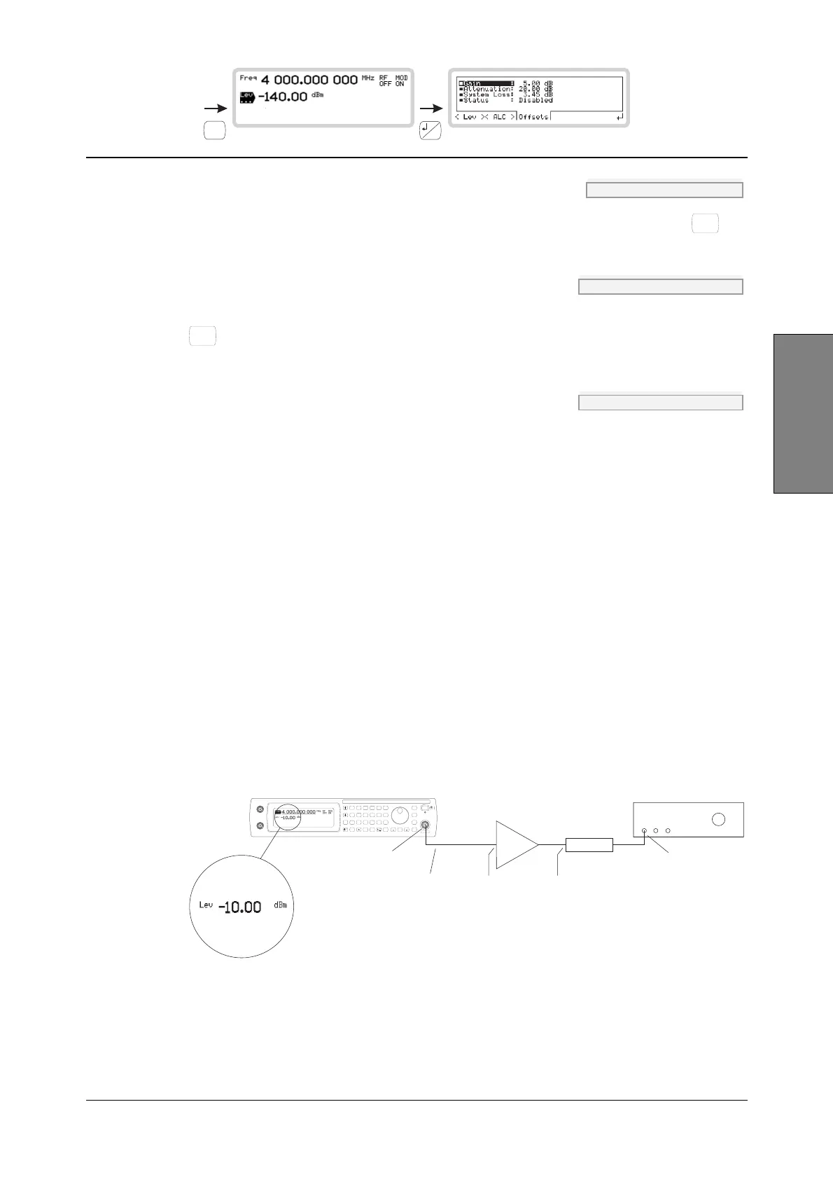
LOCAL OPERATION RF LEVEL
SIG
GEN
B5196
...
B5195
3-31
Carrier/RF
Attenuation POW:OFFS:ATT page 4-150
Enter the attenuation of the external device (a positive value only, or 0), terminating with
Hz
rad
dB
.
System Loss POW:OFFS:LOSS page 4-151
Enter a figure for power loss through the cabling (a positive value only, or 0), terminating with
Hz
rad
dB
.
Status POW:OFFS:STAT page 4-151
Use the numeric keypad to choose whether the offsets are enabled or disabled.
Offsets example
You can calculate the power present at the instrument’s output from the following equation:
Actual RF output power = displayed RF level
−
gain value + attenuation value + system loss value
So for example, if:
DUT requires −10 dBm at input,
Attenuation consists of a 5 dB pad,
Gain is 20 dB,
System loss is 3 dB:
Actual RF output power = −10 dBm − 20 dB +5 dB + 3 dB
= −22 dBm.
But note that you do not see this figure displayed! The instrument displays –10 dBm, the level
required by the DUT.
C5445
DUT
Cable loss
3dB
22 dBm
at output
10 dBm
at input
25 dBm
5 dBm
Gain
Attenuation
SIG
GEN
SWEEP
UTIL
SAVE
RECALL
<TAB>
...
MOD
MODE
GHz
MHz
kHz
Hz
rad
s
ms
%
V
mV
V
dB
KNOB/
STEP
ERROR
STATUS
SOURCE
ON/OFF
RF OUTPUT
50
MOD
ON/OFF
RF
ON/OFF
x10
7
8
9
6
5
4
1
0
.
2
3
10
I
EXT AM
Q
EXT FM
LOCAL
ENTER
50 /
100k
50 /
100k
REVERSEPOWER
50WMAX
20
dB
5dB
Fig. 3-25 Offsets example


 To Next Page