OPERATIONAL VERIFICATION TESTING
6-13
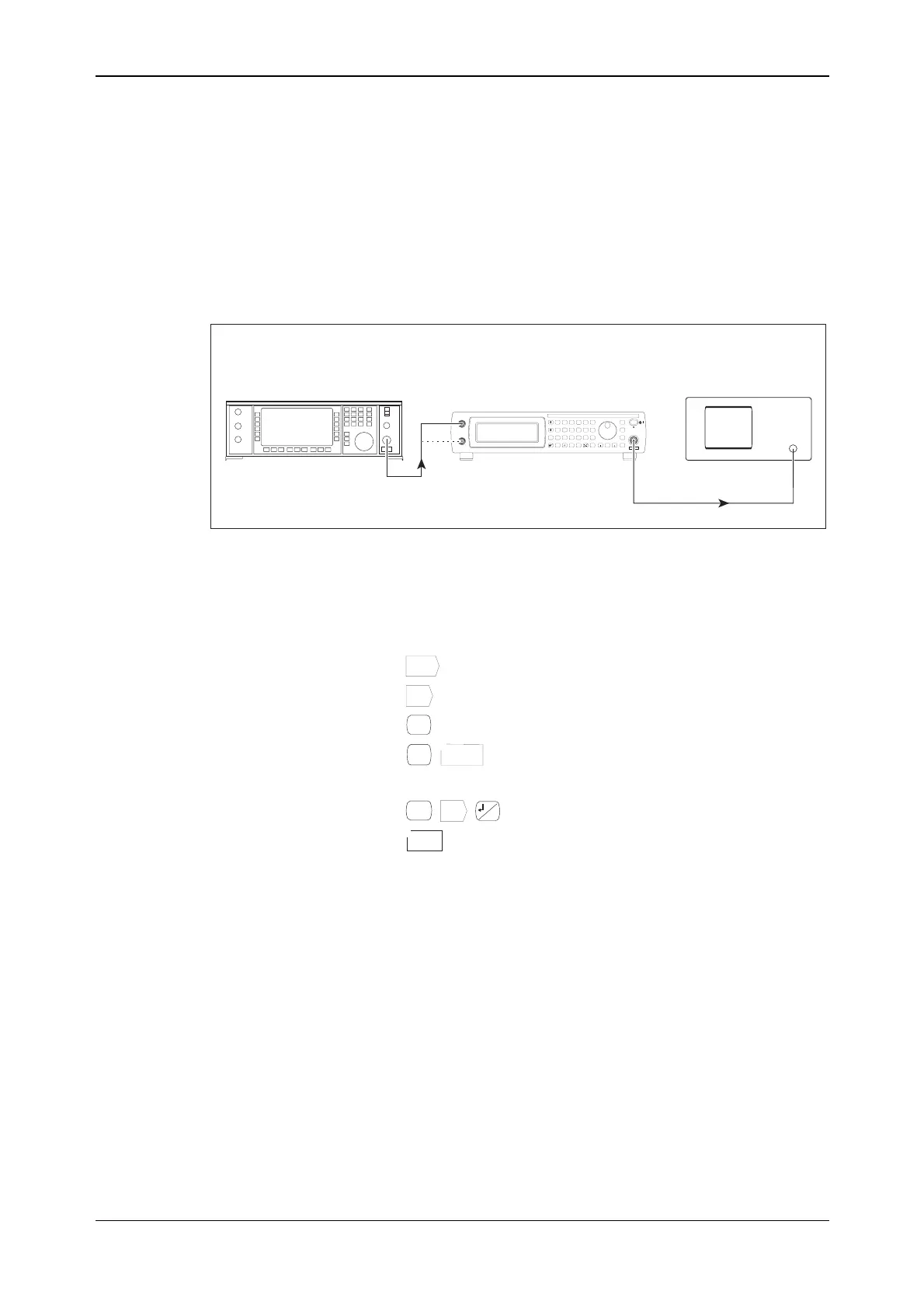
Digital modulation tests
External IQ inputs
The digital modulation test ensures functionality of each of the IQ modulators.
A signal generator is used to stimulate the I and Q inputs in turn. The IQ modulator response is
viewed on a spectrum analyzer.
C5486
UUT
Spectrum analyzer
Signal generator
RF
OUTPUT
RF
OUTPUT
RF INPUT
EXT I/EXT Q
INPUTS
SIG
GEN
IQ
MOD
ANALOG
MOD
RECALL
SAVE
UTIL
<TAB>
...
SWEEP
GHz
MHz
kHz
Hz
rad
s
ms
%
V
mV
mV
dB
KNOB/
STEP
ERROR
STATUS
SOURCE
ON/OFF
RF OUTPUT
50W
MOD
ON/OFF
RF
ON/OFF
x10
7
8
9
6
5
4
1
0
.
2
3
10
¸
EXT I
EXTAM
EXT Q
EXT FM
LOCAL
ENTER
50 /
100k
W
W
50 /
100k
W
W
REVERSEPOWER
50WMAX
Fig. 6-4 RF output level test setup
1 Connect the test equipment as shown in Fig. 6-4.
2 On the UUT set:
Freq
...
375 [MHz]
Lev
...
0 [dB]
RF
ON/OFF
IQ
MOD
Ext IQ
1
3 On the UUT set:
SIG
GEN
IQ
...
...
<Self-Cal>
Start
Cal
0
Ensure that the IQ cal has successfully completed.
4 Set the signal generator to carrier frequency 500 kHz, RF output level 500 mV.
5 Set the spectrum analyzer to center frequency 375 MHz, span 22 MHz, ref level 0 dB,
1 dB/div, and set the trace to max hold.
6 Using the rotary control, tune the signal generator's carrier frequency up to 10 MHz in
10 kHz steps and view the sideband responses on the spectrum analyzer.
7 Using the marker facility on the spectrum analyzer, check the response of the upper and
lower sidebands at 5 MHz and 10 MHz offsets, relative to the ±500 kHz offset level.
8 Repeat 3 to 7 for remaining carrier frequencies in Table 6-6.
9 Connect the signal generator's output to the EXT Q input of the UUT and repeat 2 to 8
above.