GENERAL INFORMATION
1-14
IQ modulation
Performance applicable in ACP and Noise modes only
IQ inputs:
BNC connector inputs, selectable 50 Ω/100 kΩ input impedance
Full-scale input (I
2
+Q
2
)
0.5
occurs for 0.5 V RMS (the level requested is obtained by
applying 0.5 V DC to either the I or Q input)
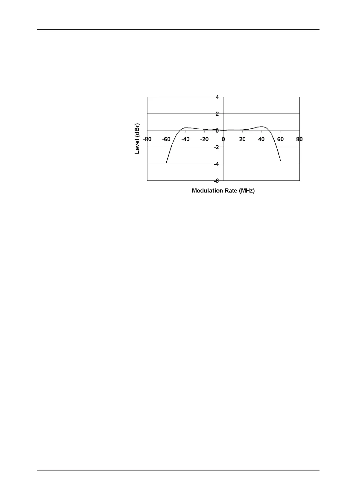
Typical IQ bandwidth
Modulation bandwidth relative to
DC:
At 23°C ± 5°C:
± 0.5 dB for frequencies DC to 5 MHz
1 dB for frequencies DC to 10 MHz
3 dB:
RF mode ≤ 2.8 GHz ≤ 6 GHz
Noise > 42 MHz, typ 50 MHz > 35 MHz, typ 45 MHz
ACP > 48 MHz, typ 55 MHz > 40 MHz, typ 50 MHz
DC vector accuracy:
Relative to full scale
(0.5 V RMS):
Static error vector
magnitude (EVM):
< 1% RMS at full scale
Magnitude error: < 0.5% RMS at full scale
Phase error: < 0.5° RMS at full scale
Residual carrier
magnitude:
For 0 V input voltage,
relative to full scale:
RF mode
Noise < −45 dBc, typically < −55 dBc
ACP < −40 dBc, typically < −50 dBc
Valid for 12 hours after executing an IQ self-calibration and within ± 5°C of the calibration
temperature. The instrument displays a warning if the time or temperature limits are
exceeded.
Static EVM and phase error measured with residual carrier magnitude removed.
IQ image suppression:
At 10 kHz modulation frequency:
Typically < −50 dBc at 10 kHz