Quick Installation Guide HEXRCHardware Manual
Quick Installation Guide
This chapter describes the order in which connections and settings should typically be made to the HEXRC.
If a custom interconnection drawing was created for your system (look for a line item on your Sales Order
under the heading “Integration”), that drawing can be found on your installation device.
The HEXRC is provided to the user fully configured for operation of a Hexapod, including servo tuning for
the user's load requirements (if provided to Aerotech).
For additional information about HEXRC , programming, utilities, and system operation see the A3200Help
file in the Aerotech folder of the Windows Start menu on the HEXRC.
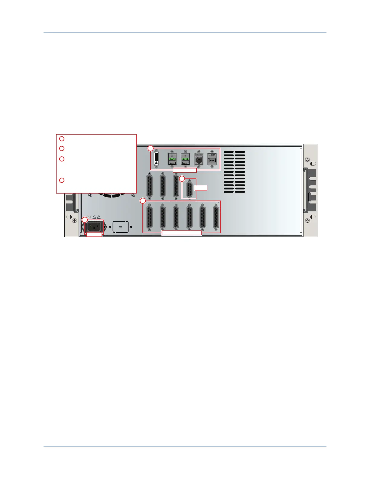
MOTOR / FEEDBACK
DIGITAL / ANALOG IO MPGA
DVI
USB2 USB3 ETHERNET FIREWIRE
ESTOP
1 2
1 2
3 4 5 6
PC Connection
2
3
Motor Power and Feedback
4
ESTOP
Connect the power source to the
AC Power input
1
2
Connect a monitor, keyboard, and
mouse (optional)
Connect each Hexapod stage cable to
a Motor/Feedback connector.
NOTE: Each axis of the HEXAPOD will be numbered
and must be connected to the corresponding
Motor/Feedback controller.
3
Connect the external Emergency Stop
(ESTOP) to the HEX RC Controller (if
the -EST3 option is present).
4
AC Power
1
Figure 1: Quick Start Connections
www.aerotech.com xi