Installation and Configuration HEXRCHardware Manual
2.3.2. Hall-Effect Inputs
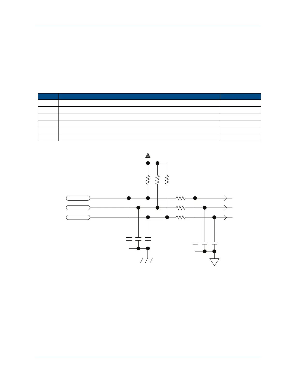
The Hall-effect switch inputs are recommended for AC brushless motor commutation but not absolutely
required. The Hall-effect inputs accept 5-24 VDC level signals. An invalid Hall state (0,0,0) or (1,1,1) will
generate a "Hall Fault" axis fault.
Refer to Section 2.3.5.1. for Hall-effect device phasing.
Table 2-9: Hall-Effect Feedback Pin Assignment
Pin# Description In/Out/Bi
5 Common --
8 Hall Effect sensor, phase A Input
9 Hall Effect sensor, phase C Input
10 Frame ground --
17 +5V power supply Output
21 Hall Effect sensor, phase B Input
10K
10K
10K
10K
10K
10K
.01UF
.01UF
.01UF
.001
.001
.001
+5V
HALL A
HALL B
HALL C
PIN-8
PIN-21
PIN-9
Figure 2-8: Hall-Effect Inputs
www.aerotech.com Chapter 2 21