Installation and Configuration HEXRCHardware Manual
2.3.5.2. DC Brush Motor Connections
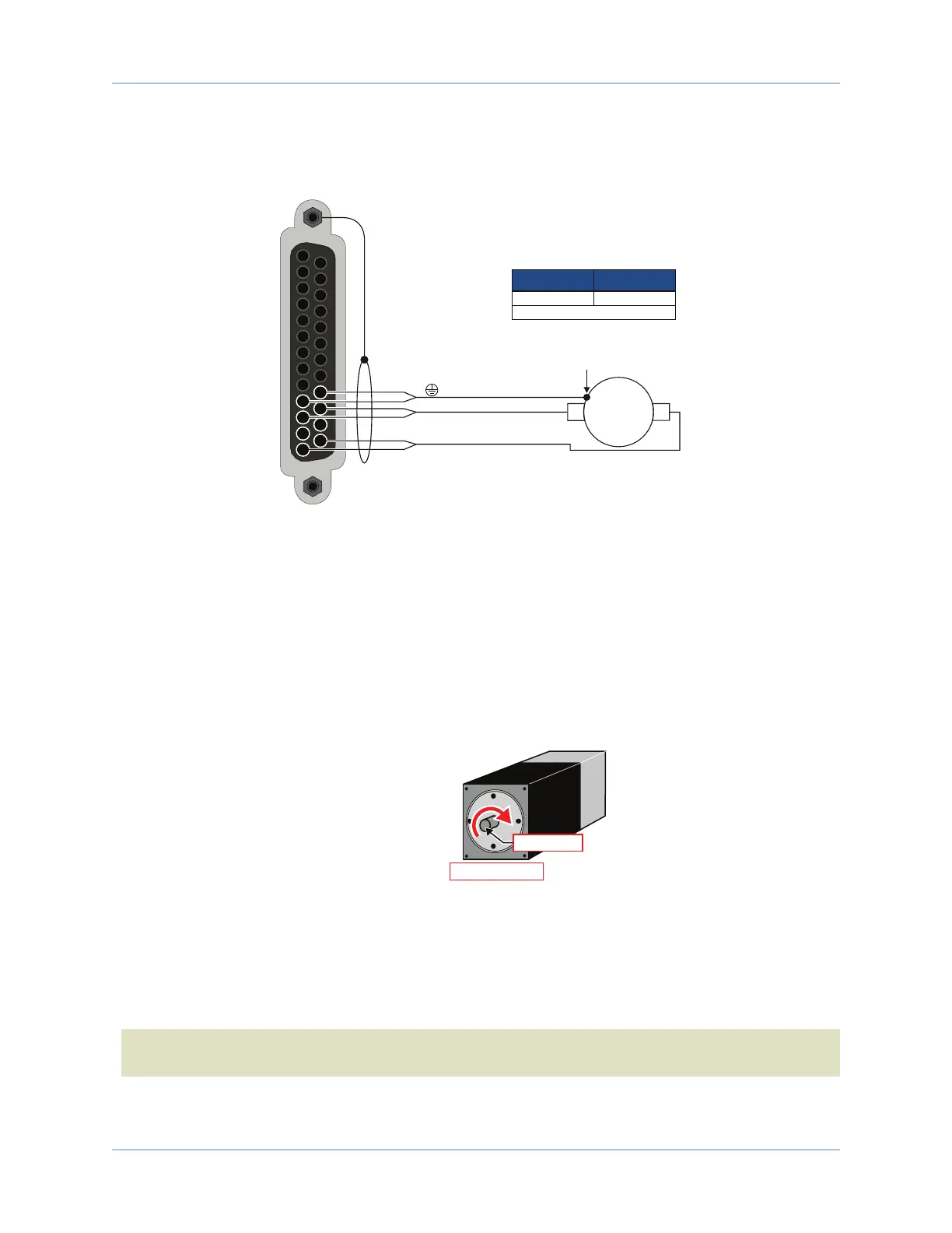
The configuration shown in Figure 2-17 is an example of a typical DC brush motor connection.
[Pins 10, 22]
ØA [Pins 11, 23]
ØC [Pins 13, 25]
13
12
11
10
25
24
23
22
To Backshell
Motor Frame
DC Brush
Motor
+
-
1. Two wires in parralel required.
(1)
22 .34
Recommended Wire Size
AWG mm
2
Figure 2-17: DC Brush Motor Configuration
DC Brush Motor Phasing
A properly phased motor means that the positive motor lead should be connected to the ØA motor terminal
and the negative motor lead should be connected to the ØC motor terminal. To determine if the motor is
properly phased, connect a voltmeter to the motor leads of an un-powered motor:
1. Connect the positive lead of the voltmeter to the one of the motor terminals.
2. Connect the negative lead of the voltmeter to the other motor terminal.
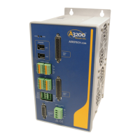
3. Rotate the motor clockwise by hand.
Motor Mounting
Flange (Front View)
Motor Shaft
ROTARY MOTOR
POSITIVE MOTION
Figure 2-18: Clockwise Motor Rotation
4. If the voltmeter indicates a negative value, swap the motor leads and rotate the motor (CW, by hand)
again. When the voltmeter indicates a positive value, the motor leads have been identified.
5. Connect the motor lead from the voltmeter to the ØA motor terminal on the HEXRC. Connect the
motor lead from the negative lead of the voltmeter to the ØC motor terminal on the HEXRC.
N O T E : If using standard Aerotech motors and cables, motor and encoder connection adjustments are
not required.
www.aerotech.com Chapter 2 29