Installation and Configuration HEXRCHardware Manual
2.2.1. ACPower Connections
AC input power to the HEXRC is applied to the AC power receptacle that is located on the rear panel. The
power cord connected to this receptacle also provides the protective earth ground connection and may serve
as a Mains disconnect. The main power switch is located on the front panel of the HEXRC. The main power
switch also functions as a 10 A breaker (supplementary protection only) for the incoming AC power. Refer to
Section 1.1. for the electrical specifications.
The HEXRC drive chassis is factory-configured for one of four specified input voltages. The factory
configured AC input voltages, along with the current requirements for the HEXRC drive chassis, are listed in
Table 2-1.
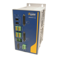
Table 2-1: Main ACPower Input Voltages and Current Requirements
ACInput Voltage Input Amps (maximum continuous) Wire Size
100 VAC 50/60 Hz 10 A 16 AWG (1.5 mm
2
)
115 VAC 50/60 Hz 10 A 16 AWG (1.5 mm
2
)
200 VAC 50/60 Hz 6 A 18 AWG (1 mm
2
)
230 VAC 50/60 Hz 5 A 18 AWG (1 mm
2
)
Environmental conditions may necessitate the need to meet additional AC wiring requirements or
specifications. AC wiring should not be bundled with signal wiring to minimize EMI coupling and
interference.
Table 2-2: ACPower Cord Wiring Specifications
Specification Value
Cord/Wire Rating 300 V
Minimum Current Capacity 10 A
Temperature Rating (Insulation)
(1)
80°C
1. The insulation rating for the ACpower wiring must be appropriately rated for the operating environment.
www.aerotech.com Chapter 2 13