HEXRCHardware Manual Installation and Configuration
2.3.5.3. Stepper Motor Connections
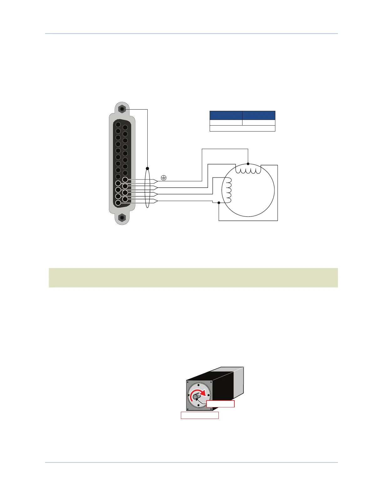
The configuration shown in Figure 2-19 is an example of a typical stepper motor connection.
In this case, the effective motor voltage is half of the applied bus voltage. For example, an 80V motor bus
supply is needed to get 40V across the motor.
13
12
11
10
25
24
23
22
A A’
B’
B
Stepper
Motor
Note the common connection
of A’ and B’ phases.
Motor Frame
To Backshell
[Pins 11, 23]
[Pins 10, 22]
[Pins 12, 24]
[Pins 13, 25]
ØA
ØB
ØC
1. Two wires in parralel required.
(1)
22 .34
Recommended Wire Size
AWG mm
2
Figure 2-19: Stepper Motor Configuration
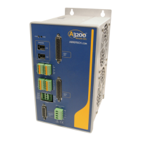
Stepper Motor Phasing
N O T E : If using standard Aerotech motors and cables, motor and encoder connection adjustments are
not required.
A stepper motor can be run with or without an encoder. If an encoder is not being used, phasing is not
necessary. With an encoder, test for proper motor phasing by running a positive motion command.
If there is a positive scaling factor (determined by the CountsPerUnit parameters) and the motor moves in a
clockwise direction, as viewed looking at the motor from the front mounting flange, the motor is phased
correctly. If the motor moves in a counterclockwise direction, swap the motor leads and re-run the
command.
Proper motor phasing is important because the end of travel (EOT) limit inputs are relative to motor rotation.
Motor Mounting
Flange (Front View)
Motor Shaft
ROTARY MOTOR
POSITIVE MOTION
Figure 2-20: Clockwise Motor Rotation
30 Chapter 2 www.aerotech.com