Installation and Configuration HEXRCHardware Manual
1
2
3
PIN-10
PIN-9
PIN-11
PIN-12
PIN-13
PIN-21
+
LOAD
–
+
LOAD
–
+
LOAD
–
+
LOAD
–
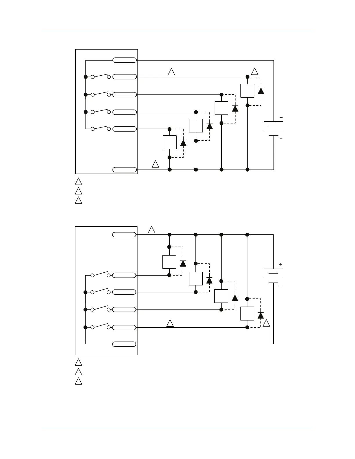
OPTOOUT0
Electronic Switches
2
Diode required on each output that drives an inductive device (coil), such as a relay.
1
Opto-Outputs 4-7 not shown.
3
Connection required to minimize glitching.
OP
5-24 VDC
CONTROLLER
OPTOOUT1
OPTOOUT2
OPTOOUT3
OM
Figure 2-23: Outputs Connected in Current Sourcing Mode
2
1
3
PIN-10
PIN-9
+
LOAD
–
+
LOAD
–
+
LOAD
–
+
LOAD
–
PIN-11
PIN-12
PIN-13
PIN-21
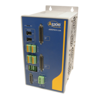
OPTOOUT0
Electronic Switches
2
Diode required on each output that drives an inductive device (coil), such as a relay.
1
Opto-Outputs 4-7 not shown.
3
Connection required to minimize glitching.
OP
5-24 VDC
OPTOOUT1
OPTOOUT2
OPTOOUT3
OM
CONTROLLER
Figure 2-24: Outputs Connected in Current Sinking Mode
www.aerotech.com Chapter 2 35