HEXRCHardware Manual Installation and Configuration
2.3.5.1. Brushless Motor Connections
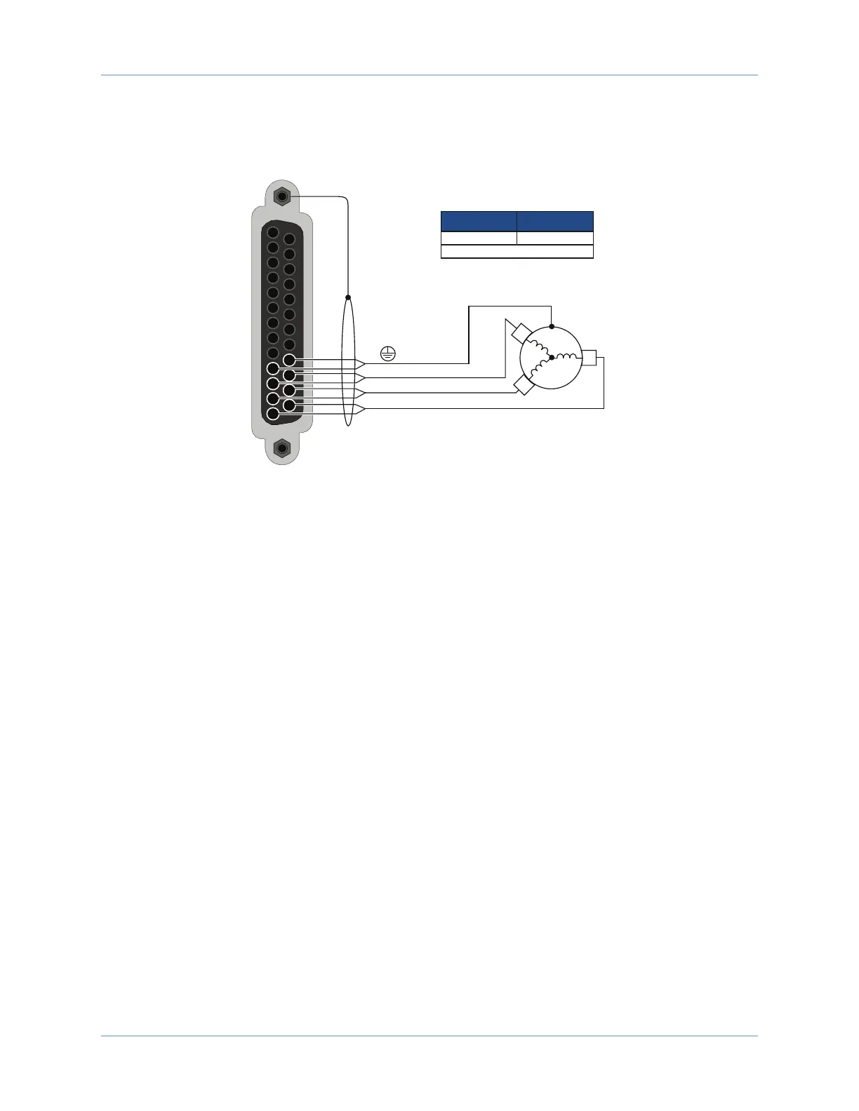
The configuration shown in Figure 2-13 is an example of a typical brushless motor connection.
13
12
11
10
25
24
23
22
AC
Brushless
Motor
Motor Frame
To Backshell
ØC [Pins 13, 25]
[Pins 10, 22]
ØA [Pins 11, 23]
ØB [Pins 12, 24]
1. Two wires in parralel required.
(1)
22 .34
Recommended Wire Size
AWG mm
2
Figure 2-13: Brushless Motor Configuration
Brushless Motor Phasing
Brushless motors are commutated electronically by the controller, typically using Hall-effect devices. If you
are using standard Aerotech motors and cables, motor phasing adjustments are not required and this section
may be skipped.
The controller requires that the Back-EMF of each motor phase be aligned with the corresponding Hall-effect
signal. To ensure proper alignment, motor, Hall, and encoder connections should be verified using one of the
following methods: powered, through the use of a test program; or unpowered using an oscilloscope. Both
methods will identify the A, B, and C Hall/motor lead sets and indicate the correct connections to the
controller.
26 Chapter 2 www.aerotech.com